Product Overview
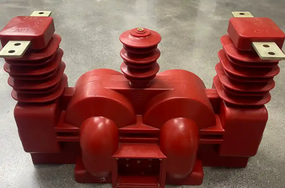
The JLSZVW-10 Combined Metering Transformer is an outdoor epoxy resin cast energy-metering unit designed for 10 kV three-phase three-wire AC power systems with a maximum system voltage of 12 kV.
Based on a two-element metering arrangement, the unit integrates voltage-transformer and current-transformer functions, allowing three-phase voltage measurement, two-phase current acquisition, and energy metering within a single device.
It is widely used for pole-mounted metering on outdoor 10 kV distribution lines and is one of the key metering devices for three-phase three-wire power systems.
Product Features
Insulation and Electrical Performance
- Outdoor epoxy resin cast insulation:
The complete unit is vacuum-cast using outdoor-grade epoxy resin. The solid insulation contains no internal air gaps and provides excellent dielectric performance. - Suitable for 12 kV systems:
The unit can withstand the operating voltage, power-frequency withstand voltage, and lightning impulse withstand voltage requirements of 10 kV systems with a maximum system voltage of 12 kV. - Low partial discharge:
Partial discharge is limited to no more than 10 pC, helping reduce insulation ageing and improve long-term operating reliability. - Oil-free outdoor construction:
The product contains no insulating oil, eliminating the risks of oil leakage, oil contamination, and oil-related fire hazards. It is suitable for outdoor environments exposed to sunlight, rain, humidity, and normal pollution. - Integrated two-element metering arrangement:
The unit is specifically designed for three-phase three-wire systems and integrates two phase-current transformer elements with a voltage-transformer element. - Simultaneous signal acquisition:
It can acquire three-phase voltage and two-phase current signals for energy metering, power calculation, and load monitoring without requiring additional external instrument transformers. - Wide ratio range:
A standard voltage ratio of 10/0.1 kV is available, while current ratios from 5/5 A to 2,000/5 A can be configured according to the connected load. - High metering accuracy:
Current transformer accuracy classes up to 0.2S and voltage transformer accuracy classes up to 0.2 are available. Classes 0.5 and 1 can also be supplied according to project requirements. - High pollution-flashover resistance:
The high-voltage side features a multi-shed insulation structure with an extended creepage distance, providing reliable resistance to surface flashover under humid and polluted outdoor conditions.
Structural and Installation Features
- Fully enclosed outdoor dry-type structure:
The complete unit is formed as an integrated cast-resin body with no exposed internal live components. - IP65 protection:
The outdoor enclosure provides an IP65 protection rating, helping prevent the ingress of rainwater, dust, and moisture. - Compact integrated design:
The voltage and current transformer functions are combined within one unit, reducing installation space, simplifying field wiring, and lowering the number of separate components required. - Alternative to oil-immersed metering units:
The dry-type structure can replace conventional oil-immersed metering boxes in suitable applications while eliminating oil maintenance requirements. - Outdoor high-voltage terminals:
The high-voltage side uses copper busbar-type terminals for convenient connection to outdoor distribution conductors. - Tinned terminal surfaces:
The high-voltage terminal contact surfaces are tin-plated to improve oxidation and corrosion resistance in outdoor environments. - Waterproof secondary terminal box:
The low-voltage terminals are housed inside an IP65 waterproof terminal box to protect the secondary circuits from rainwater and moisture. - Clear terminal identification:
High-voltage terminals and secondary voltage and current circuits are clearly marked and grouped separately to reduce the risk of wiring errors. - Flexible installation:
The unit supports outdoor pole-mounted crossarm installation and indoor switchgear installation. - High mechanical stability:
The mounting structure provides reliable vibration and wind resistance and can withstand normal outdoor wind, rain, and snow loads when correctly installed.
Operation and Maintenance Features
- Low-maintenance operation:
The dry-type, oil-free construction eliminates oil leakage, oil replacement, and oil-related fire risks. - High mechanical strength:
The outdoor epoxy resin body provides reliable impact resistance, ageing resistance, and corrosion resistance. - Wide operating temperature range:
The unit can operate at ambient temperatures from -40°C to +70°C. The epoxy resin maintains stable insulation and mechanical properties without becoming brittle or deformed. - Suitable for outdoor temperature variations:
The product can withstand significant day-to-night and seasonal temperature changes. - High operational reliability:
The voltage and current transformer components use high-quality magnetic cores and winding materials, providing low operating losses and limited temperature rise. - Stable long-term accuracy:
The unit is designed to maintain stable metering accuracy with minimal error drift during long-term operation. - Overvoltage withstand capability:
The product can withstand switching and lightning overvoltages within its specified insulation level.
Technical Specifications
Electrical Parameters
| Parameter | Specification |
|---|---|
| Applicable System Voltage | 10 kV AC, Um = 12 kV |
| Rated Frequency | 50 Hz |
| Voltage Ratio | 10/0.1 kV, customizable |
| Current Ratio | 5/5 A to 2,000/5 A, customizable |
| Voltage Transformer Accuracy Class | Class 0.2 / 0.5 / 1 |
| Current Transformer Accuracy Class | Class 0.2S / 0.5S / 0.5 |
| Power-Frequency Withstand Voltage | 42 kV for 1 minute at the high-voltage terminal, without breakdown |
| Lightning Impulse Withstand Voltage | 75 kV peak, without breakdown |
| Partial Discharge | ≤10 pC |
| Insulation Resistance | ≥1,000 MΩ between high voltage, low voltage, and earth |
Structural and Material Parameters
| Parameter | Specification |
|---|---|
| Insulating Medium | Fully cast outdoor-grade epoxy resin |
| Protection Rating | IP65 |
| Installation Type | Outdoor pole-mounted crossarm installation or indoor switchgear installation |
| Thermal Class | Class B, 130°C |
Environmental Parameters
| Parameter | Specification |
|---|---|
| Installation Altitude | ≤2,000 m; high-altitude versions available |
| Operating Temperature | -40°C to +70°C |
| Storage Temperature | -40°C to +85°C |
| Relative Humidity | ≤95%, non-condensing |
Applicable Standards
| Standard | Description |
|---|---|
| GB 1207 | Voltage Transformers |
| GB 1208 | Current Transformers |
| GB/T 17215 | Electricity Metering Equipment |
| DL/T 448 | Technical Administrative Code for Electric Energy Metering |
Applications
Applicable Power System
The JLSZVW-10 Combined Metering Transformer is suitable for 10 kV three-phase three-wire AC power systems with a maximum system voltage of 12 kV.
Typical Applications
- Pole-mounted energy metering on outdoor 10 kV distribution lines
- Energy metering and load monitoring in indoor medium-voltage switchgear
- Box-type substations
- Switching and distribution stations
- 10 kV distribution systems in industrial and mining enterprises
- Commercial buildings and industrial parks
- Energy data acquisition in power automation systems
- Power monitoring, control, and load management systems
Main Functions
The combined metering transformer converts the system high voltage and primary current into standardized secondary signals:
- Secondary voltage: 100 V
- Secondary current: 5 A
These signals can be supplied to:
- Three-phase three-wire energy meters
- Metering instruments
- Load-monitoring equipment
- Power data acquisition devices
- Energy management systems
- Power automation equipment
The unit supports:
- Energy metering
- Power calculation
- Load monitoring
- Electrical parameter acquisition
- Energy consumption management
It also provides electrical isolation between the primary power system and the secondary metering circuits, helping ensure the safe operation of connected metering equipment.
Operating Conditions
Normal Operating Conditions
- Installation altitude: no more than 2,000 m
- Ambient temperature: -40°C to +70°C
- Severe or sudden temperature changes should be avoided
- Relative humidity: no more than 95%, non-condensing
- The environment should be free from corrosive gases
- Flammable or explosive substances are not permitted
- Severe vibration and mechanical impact should be avoided
- Outdoor models can withstand normal sunlight, rain, frost, and wind erosion
- Outdoor pole-mounted crossarm or indoor switchgear installation
- Severe corrosion, salt spray, and heavy sand or dust conditions should be avoided unless a customized version is used
Special Operating Conditions
Customized products are required for:
- Installation altitudes above 2,000 m
- Ambient temperatures outside the range of -40°C to +70°C
- Severe pollution or salt-spray environments
- Chemically corrosive environments
- Strong wind or severe sand and dust conditions
- High-intensity ultraviolet exposure
- Non-standard voltage ratios
- Non-standard current ratios
- Special mounting dimensions
Installation and Maintenance
Installation Requirements
- Pre-installation inspection:
Inspect the combined metering transformer and confirm that the epoxy resin body is free from cracks, bubbles, mechanical damage, and other visible defects. Check that all terminal markings are clear and that the supplied accessories are complete. Verify that the model, specifications, voltage ratio, current ratio, and metering accuracy classes match the system design requirements. - Mounting:
Select a suitable crossarm and mounting bracket according to the installation arrangement. Secure the metering transformer in the specified position and confirm that there is no looseness, displacement, or uneven mechanical loading. The mounting surface should be level. Outdoor pole-mounted installations must meet the applicable wind-load and anti-overturning requirements. - High-voltage-side connection:
Connect the high-voltage terminals according to the system design. Ensure that all connections are securely tightened and provide reliable electrical contact. Maintain adequate electrical clearance between high-voltage conductors, earthed components, and other live parts. Outdoor connections must be protected against water ingress and corrosion. Conductive joint compound should be applied to the terminal contact surfaces where required to reduce oxidation. - Secondary-side connection:
Connect the voltage and current secondary terminals to the energy meter according to their markings. The current transformer secondary circuit must never be left open while the primary circuit is energized. The voltage transformer secondary circuit must never be short-circuited. The current secondary circuit must be reliably earthed at one point in accordance with the system design and applicable electrical safety requirements. Ensure that the waterproof secondary terminal box is correctly closed and sealed after wiring. - Insulation inspection:
After installation, measure the insulation resistance between:- High voltage and low voltage
- High voltage and earth
- Low voltage and earth
Maintenance Requirements
- Regularly inspect the epoxy resin body for cracks, mechanical damage, discharge marks, and contamination.
- Check the high-voltage terminals for looseness, oxidation, corrosion, and abnormal heating.
- Inspect the waterproofing and corrosion protection of all outdoor connections.
- Confirm that the secondary terminal box remains properly sealed.
- Regularly inspect high-voltage and low-voltage connections for looseness, overheating, and discoloration.
- Confirm that the current secondary circuit remains correctly connected and reliably earthed.
- Periodically verify the metering accuracy and compare the meter readings with the specified error limits of the combined metering transformer.
- Periodically test the insulation resistance and confirm that the insulation performance remains within the specified requirements.
- Clean dust and contamination from the product surface.
- Regularly clean the insulating sheds to reduce the risk of pollution flashover.
- Prevent oil and corrosive substances from contacting the epoxy resin body.
- If cracking, electrical discharge, overheating, or excessive metering error is detected, immediately de-energize and inspect the equipment. Replace the unit where necessary.
Precautions
- The current transformer secondary circuit must never be left open while the primary system is energized. The voltage transformer secondary circuit must never be short-circuited. Either condition may produce hazardous overvoltage or overcurrent and create a serious risk to equipment and personnel.
- During maintenance, the current secondary circuit must be securely short-circuited and earthed before disconnection. The voltage secondary circuit must be safely isolated before work begins.
- Avoid impact or collision with the epoxy resin body and high-voltage terminals during transportation and installation. Mechanical damage may reduce insulation performance and pollution-flashover resistance.
- Use suitable insulated conductors for high-voltage connections. Maintain adequate electrical clearance from earthed components and other live parts to prevent phase-to-phase or phase-to-earth discharge.
- Confirm the correct phase sequence during three-phase wiring. Incorrect phase connections may affect metering accuracy.
- The equipment must be reliably earthed. The grounding terminal on the base must be securely connected to the grounding busbar.
- Outdoor installations must comply with the applicable lightning protection and earthing requirements.
- Store the product in a dry, ventilated, and shaded environment. Avoid direct sunlight, high temperatures, moisture, compression, and mechanical impact.
- Installation, commissioning, and maintenance must be carried out by qualified electrical personnel in accordance with applicable electrical safety procedures.
- Outdoor connections must be properly protected against rainwater ingress and corrosion.
- The metering transformer must pass verification by the relevant local metrology authority before being put into service where such verification is required.
Standard Supply List
| No. | Item | Function |
|---|---|---|
| 1 | JLSZVW-10 Outdoor Two-Element Combined Metering Transformer | Main device for voltage and current transformation, electrical isolation, and energy metering |
| 2 | Mounting Brackets, Bolts, and Washers | Used to secure the metering transformer during installation |
| 3 | Secondary Terminal Box and Terminal Cover | Protect the low-voltage terminals against incorrect connection, short circuits, and water ingress |
| 4 | Product Instruction Manual | Provides installation, operation, maintenance, wiring, and outdoor mounting guidance |
| 5 | Product Certificate, Factory Test Report, and Metrological Verification Certificate | Provide product quality and performance documentation, including voltage-ratio, current-ratio, and accuracy test data |
Applicable Standards and Certification
The product complies with the following standards:
- GB 1207, Voltage Transformers
- GB 1208, Current Transformers
- GB/T 17215, Electricity Metering Equipment
- DL/T 448, Technical Administrative Code for Electric Energy Metering
The product has passed the applicable type tests and metrological verification. Its performance meets the energy metering requirements of 10 kV three-phase three-wire power systems.