
Introduction
Medium voltage cable systems are widely used in power distribution networks where electrical reliability, insulation safety, and maintenance efficiency are essential. In these systems, cable connection points are not just simple joints. They are critical interfaces between cables, switchgear, ring main units, compact substations, cable branch boxes, and distribution transformers. If the connection structure is not properly selected or installed, the whole system may face risks such as insulation failure, overheating, poor contact, partial discharge, or difficult maintenance.
A Separable Connector is designed to make medium voltage cable connections safer, more organized, and easier to manage. Unlike permanent cable joints that are difficult to inspect or remove, a Separable Connector allows cables and equipment interfaces to be connected through a modular and insulated structure. This makes it useful in systems that require reliable connection, future expansion, easier testing, and safer maintenance access.
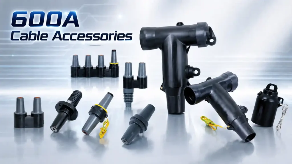
In modern medium voltage distribution, a Separable Connector is often used together with bushings, busbars, protective caps, deadbreak connectors, T-shaped connectors, and other Medium Voltage Cable Accessories. The purpose is not only to complete the electrical connection, but also to support insulation coordination, mechanical stability, environmental protection, and long-term system reliability.
This article explains what a Separable Connector does, how it improves safety, what should be checked before selection, and how it works with other medium voltage cable connection components.
What Is a Separable Connector and Why Is It Used in Medium Voltage Cable Systems?
Basic function of a Separable Connector
A Separable Connector is a specially designed medium voltage cable accessory used to connect power cables with electrical equipment such as switchgear, transformers, ring main units, and cable branch boxes. Its main function is to create a safe, insulated, and removable connection between the cable and the equipment interface.
The word “separable” is important. It means the connector can be connected or disconnected from the equipment interface under specified operating conditions. This gives the system more flexibility than a fixed cable joint. When maintenance, testing, replacement, or system expansion is needed, the connection structure can be handled more conveniently.
In medium voltage systems, connection points must withstand electrical stress, thermal stress, mechanical pressure, and environmental influence. A Separable Connector helps manage these challenges by combining insulation, shielding, sealing, and mechanical contact into one structured component.
Common installation positions
A Separable Connector is commonly used in compact and enclosed medium voltage power systems. These systems often have limited installation space, so the connection structure must be compact, standardized, and easy to operate.
Common applications include ring main units, compact substations, medium voltage switchgear, pad-mounted transformers, cable branch boxes, renewable energy collection systems, and industrial power distribution networks. In these applications, a Separable Connector helps connect cables to bushings or other interface components while maintaining insulation safety and installation consistency.
For example, in a ring main unit, the connector may be used to connect incoming and outgoing cables to the switchgear interface. In a compact substation, it may connect the medium voltage cable to a transformer bushing. In a cable branch box, it may support multi-way cable distribution and future network expansion.
Why separable design matters
The separable structure is valuable because medium voltage systems are not always static. A power distribution network may need inspection, load adjustment, equipment replacement, or cable route modification over time. If every connection is fixed and difficult to remove, maintenance becomes slower and more complicated.
A Separable Connector allows the system to be more serviceable. It helps technicians inspect and manage the cable connection point more clearly. It also supports a more modular system layout, especially where future expansion is expected.
This does not mean any connector can be removed casually. Medium voltage operation must always follow correct procedures, safety rules, and equipment specifications. However, compared with many fixed connection methods, a properly selected Separable Connector can make the connection system more flexible and easier to maintain.
Table 1: Common Applications of a Separable Connector in Medium Voltage Systems
| Application Area | Typical Connection Point | Main Purpose |
| Ring main unit | Cable to bushing interface | Supports compact and insulated cable connection |
| Compact substation | Transformer or switchgear side | Improves installation safety and maintenance access |
| Cable branch box | Multi-way cable connection | Supports cable distribution and system expansion |
| Renewable energy station | Medium voltage collection system | Helps connect cables in structured power networks |
| Industrial power system | Switchgear and equipment interface | Improves operational reliability and serviceability |
How Does a Separable Connector Help Improve Electrical Safety?
Insulation protection around the connection point
Electrical safety is one of the main reasons for using a Separable Connector in medium voltage cable systems. At the cable termination point, the electric field can become concentrated if the structure is not properly controlled. This may increase the risk of partial discharge, insulation aging, flashover, or breakdown.
A high-quality Separable Connector is designed with insulation and shielding structures that help control electrical stress. The insulation layer provides dielectric strength, while the semiconductive shielding layer helps maintain a more stable electric field distribution. This is especially important in enclosed medium voltage equipment, where the distance between live parts, grounded parts, and surrounding components may be limited.
The connector also helps reduce the risk of exposed conductive parts. In many medium voltage systems, touch safety and insulation coverage are important design considerations. A properly installed Separable Connector can help keep the connection point protected and reduce direct exposure risks during normal operation.
Shielding, grounding, and stress control
A Separable Connector is not only about physical connection. It also helps manage electrical stress through shielding and grounding design. The outer semiconductive layer is usually connected to the grounding system, which helps keep the connector surface at a safer potential level.
Stress control is also important where the cable shield is cut back and the conductor is connected to the equipment interface. Without proper stress control, the electric field may become uneven at the end of the cable insulation. This can weaken the insulation system over time.
By using a connector designed for the correct voltage class and cable structure, the system can achieve better insulation coordination. This improves long-term reliability and reduces the possibility of hidden defects developing at the connection point.
Deadbreak connection for stable medium voltage systems
Many 600A Separable Connector structures are designed as deadbreak connectors. A deadbreak connector is intended to be connected or disconnected only when the circuit is de-energized. This type of design is often used where higher current capacity and stable medium voltage connection are required.
Deadbreak connectors are different from loadbreak connectors. A loadbreak connector can be operated under specific load conditions, while a deadbreak connector requires the circuit to be safely isolated first. Because of this, deadbreak connectors are often selected for systems where secure, high-current, and long-term connection performance is more important than frequent live operation.
For systems using 600A connection structures, deadbreak T connectors, bushings, and related accessories are commonly used to create a strong and insulated cable interface. When matched correctly, they can support stable current carrying capacity and better mechanical connection strength.
Protection against moisture, dust, and outdoor conditions
Medium voltage systems may operate in harsh environments. Humidity, dust, temperature change, salt fog, and pollution can all affect cable connection reliability. A Separable Connector must therefore provide not only electrical insulation but also environmental sealing.
Good sealing helps prevent moisture from entering the connection interface. Moisture can reduce insulation performance and increase the risk of tracking or discharge. Dust and pollution can also affect surface insulation, especially in outdoor or semi-outdoor installations.
For this reason, connector material, sealing structure, and installation quality are all important. Even a well-designed Separable Connector may not perform properly if it is installed without following the correct procedure. Cable preparation, interface cleaning, lubrication, torque control, grounding, and final inspection should all be treated carefully.
What Should Be Checked Before Choosing a Separable Connector?
Voltage class and insulation level
The first factor to check is the voltage class. A Separable Connector must match the rated voltage of the power system. Common medium voltage applications may involve 15kV, 24kV, or other voltage levels depending on the network design and equipment standard.
If the connector voltage rating is not suitable, the insulation system may not provide enough protection. This can create safety risks and shorten service life. The selected connector should also match the required insulation level, impulse withstand voltage, and system grounding conditions.
Voltage matching is not only a nameplate issue. The actual operating environment, possible overvoltage, switching conditions, and protection coordination should also be considered. In medium voltage systems, conservative and correct selection is usually better than choosing based only on minimum requirements.
Current rating and thermal performance
Current rating is another key selection factor. A Separable Connector must carry the rated current of the system without overheating. In many medium voltage cable connection systems, 200A and 600A are common current levels.
For higher capacity systems, a 600A Separable Connector may be required. The connector must have a stable conductive path, reliable contact pressure, and proper material performance. If the connection is loose or mismatched, heat may build up at the contact point. Long-term overheating can damage insulation, reduce contact quality, and increase failure risk.
Thermal performance is closely related to installation quality. Even if the connector has the correct current rating, poor cable preparation or incorrect assembly may still cause resistance at the connection point. This is why installation tools, torque values, and inspection procedures should not be ignored.
Cable size and interface compatibility
A Separable Connector must match the cable size and insulation diameter. Medium voltage cables may differ in conductor cross-section, insulation thickness, shielding structure, and outer diameter. If the connector does not match the cable properly, the installation may become difficult or unreliable.
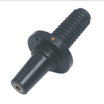
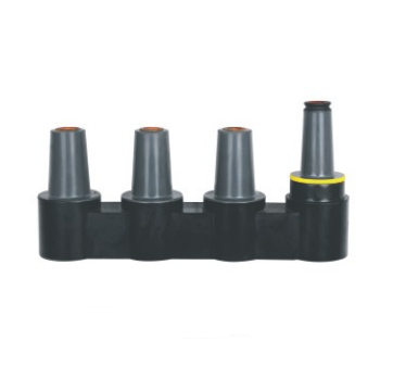
The equipment interface must also be checked. Different systems may use different bushing types, connector shapes, or connection arrangements. For example, a T-shaped connector, deadbreak bushing, front connector, rear connector, busbar, or protective cap may be required depending on the system layout.
This is where the relationship between a Separable Connector and other Medium Voltage Cable Accessories becomes important. The connector should not be selected as an isolated part. It should be selected as part of the complete connection system.
Installation space and cable routing
Medium voltage cabinets and compact substations often have limited internal space. The cable bending radius, connector angle, equipment position, and maintenance space all affect the final installation result.
If the connector is too large or the cable route is not suitable, installation may create mechanical stress on the cable or connector interface. This can reduce long-term reliability. In some cases, a different connector shape or connection method may be needed to match the actual cabinet design.
Before choosing a Separable Connector, it is helpful to review the system layout drawing, equipment interface, cable entry direction, grounding route, and maintenance access area. This can reduce problems during installation and commissioning.
Table 2: Key Selection Factors for a Separable Connector
| Selection Factor | What to Check | Why It Matters |
| Voltage class | 15kV, 24kV, or system-specific rating | Ensures the insulation level matches the power network |
| Current rating | 200A or 600A connection requirement | Prevents overheating and capacity mismatch |
| Connector type | T connector, deadbreak connector, bushing, busbar, protective cap | Matches the actual connection structure |
| Cable compatibility | Cable size, insulation diameter, conductor type | Supports proper installation and electrical contact |
| Equipment interface | Switchgear, transformer, RMU, or cable box interface | Avoids mechanical and electrical mismatch |
| Environment | Indoor, outdoor, humid, dusty, or high-temperature conditions | Improves long-term reliability |
How Does a Separable Connector Support Easier Maintenance and System Expansion?
Clearer connection structure for inspection
Maintenance efficiency is another important advantage of a Separable Connector. In medium voltage systems, connection points must be inspected during installation, testing, operation, and troubleshooting. A clear and modular connector structure makes this process easier.
When a cable connection is made through a standardized Separable Connector, technicians can better identify the connection path, grounding position, accessory type, and interface arrangement. This helps reduce confusion during maintenance work.
A well-organized connector system can also support testing procedures. For example, when equipment inspection or cable testing is required, the separable design may make it easier to isolate or access certain connection points under the correct safety procedure.
Easier replacement when system parts change
Power distribution systems may change over time. Equipment may be upgraded, cables may be replaced, or system capacity may be expanded. If the connection method is too fixed, any change may require more labor and longer downtime.
A Separable Connector helps create a more modular connection system. When a compatible connector, bushing, busbar, or protective cap is used, future replacement can be more manageable. This is useful in compact substations, ring main units, and cable branch systems where equipment access may be limited.
Of course, replacement still requires skilled operation and strict safety control. Medium voltage systems must be de-energized, grounded, and verified according to applicable procedures before maintenance work. The benefit of the Separable Connector is that the physical connection structure is designed to support such maintenance more efficiently.
Better support for network expansion
Many medium voltage distribution systems are built with future expansion in mind. New loads, renewable energy sources, industrial equipment, or additional distribution branches may need to be connected later. A Separable Connector can support this kind of planning by making the cable interface more adaptable.
For example, a cable branch box may need additional cable ways in the future. A compact substation may need connection adjustment after equipment upgrading. A renewable energy project may need medium voltage collection system expansion as capacity increases. In these cases, modular cable connection accessories can help reduce redesign complexity.
This does not mean that expansion can be done without engineering review. Load capacity, protection coordination, cable rating, equipment rating, and system short-circuit level must still be checked. However, using a suitable Separable Connector system can make the physical connection side more flexible.
Reducing downtime through organized design
Downtime can be costly in medium voltage power systems. While a Separable Connector cannot eliminate downtime by itself, it can help reduce unnecessary installation and maintenance difficulty when used correctly.
A clear connector structure allows technicians to locate connection points more quickly. Properly matched accessories can reduce installation errors. Standardized components can also make replacement and inspection more predictable.
In practical terms, the benefit is not only electrical performance but also operational convenience. A well-designed Separable Connector system supports safer maintenance planning, clearer work procedures, and better long-term management of cable connection points.
How Can Separable Connectors Work with Other Medium Voltage Cable Accessories?
A connector is part of a complete cable accessory system
A Separable Connector is rarely used alone. In a complete medium voltage cable connection system, it may work with bushings, busbars, insulated protective caps, surge arresters, grounding kits, cable adapters, stress control components, and other Medium Voltage Cable Accessories.
This system-based view is important because medium voltage reliability depends on the compatibility of all connection parts. Even if one connector is well designed, the system may still face risks if it is matched with the wrong bushing, incorrect cable size, unsuitable protective cap, or incompatible interface.
Therefore, selection should consider the whole connection structure. The voltage class, current rating, cable specification, equipment interface, grounding arrangement, and installation environment should be checked together.
Why matching accessories matter
Medium voltage cable connection requires accurate mechanical and electrical matching. If accessories from different systems are combined without proper verification, the result may be poor contact, insufficient insulation distance, weak sealing, or mechanical stress.
For example, a 600A deadbreak connector should be matched with a compatible 600A bushing or busbar structure. An insulated protective cap should match the interface it is intended to cover. A T-shaped connector should match the cable size and equipment layout.
Matching accessories also help simplify installation. When components are designed to work together, the installation sequence becomes clearer, the interface is more predictable, and the final connection is easier to inspect.
Where product structure should be considered
In many medium voltage projects, different connection structures may be required in the same system. Some positions may need busbar connection. Some may need integral deadbreak bushings. Others may need T-shaped front connectors, deadbreak connectors, or insulated protective caps.
For this reason, the connector system should be selected according to actual engineering needs rather than only by product name. The same system may require 15kV or 24kV voltage levels, 200A or 600A current ratings, front and rear connection arrangements, or transition structures between different interfaces.
When the system requires 600A deadbreak connection, busbar connection, bushing interfaces, protective caps, or 600A/200A transition solutions, related product structures should be reviewed together.
Natural product reference
For projects that require medium voltage separable connection solutions, YIEOU can be considered for related Separable Connector and Medium Voltage Cable Accessories options. Its product range includes solutions such as JY HMP-15kV/600A/-200A mixed busbars, JY YMP-15kV 200A/600A shaped busbars, JY MP-15/24kV 600A busbars, JY JCTG-15kV 600A integral deadbreak bushings, JY JYM-600 15kV/24kV 600A insulated protective caps, JY ZHT-15kV 600/200 integral deadbreak bushings, JY TTL-15kV/24kV 600A deadbreak T connectors, JY QJT-600 15kV/24kV 600A T-shaped American front connectors, JY TIIT-/600 15kV/24kV 600A TIIT deadbreak connectors, and JY TT-600 15kV/24kV 600A T deadbreak connectors.
These product structures should be selected according to actual voltage class, current rating, cable size, equipment interface, installation layout, and maintenance requirements.
Conclusion
A Separable Connector plays an important role in medium voltage cable systems because it helps make cable connection safer, more flexible, and easier to maintain. It is not just a connector for joining cables and equipment. It is part of a complete insulated connection structure that affects electrical safety, installation quality, maintenance efficiency, and long-term system reliability.
When choosing a Separable Connector, several factors should be checked carefully, including voltage class, current rating, cable size, connector type, equipment interface, installation space, and environmental conditions. It should also be considered together with related Medium Voltage Cable Accessories, because the performance of the whole connection system depends on proper matching.
For medium voltage systems that require 15kV or 24kV 600A connection structures, deadbreak connectors, busbars, bushings, protective caps, or T-shaped connector solutions, YIEOU provides related options that can be reviewed according to real project requirements.