
Introduction
Reliable medium-voltage power distribution depends on more than cables, transformers, switchgear, and protection devices. The interfaces between these components must carry current, maintain insulation, control electrical stress, resist contamination, and remain accessible throughout the service life of the system.
A poorly prepared or incorrectly matched cable interface may lead to localized heating, partial discharge, moisture ingress, insulation deterioration, or unexpected outages. These problems can occur even when the cable and equipment are individually suitable for the application. The weak point is often the transition between the cable insulation system and the equipment connection interface.
A Separable Connector provides a removable and insulated connection between a medium-voltage cable and compatible electrical equipment. It is commonly used with ring main units, transformers, compact switchgear, cable branch boxes, prefabricated substations, and other distribution equipment.
Compared with a permanently assembled termination, a Separable Connector can make installation, equipment replacement, testing, grounding, circuit isolation, and future system expansion more manageable. The connection can be separated and reconnected under defined conditions without rebuilding the entire cable termination every time maintenance is required.
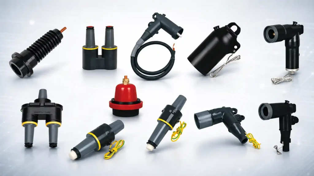
However, not every Separable Connector performs the same function. Loadbreak elbow connectors, bushing inserts, casing seats, insulation caps, grounding elbows, junctions, extension connectors, and surge arresters all serve different purposes. Products that appear similar may still be incompatible in terms of voltage rating, interface dimensions, current capacity, cable size, or operating method.
For this reason, selection must go beyond product appearance or nominal voltage. Engineers and installers should consider system voltage, rated current, cable conductor size, insulation diameter, equipment interface, installation environment, maintenance requirements, switching duty, and protection coordination.
This article explains how a Separable Connector works, how it simplifies installation and maintenance, what should be checked before selection, and how correct installation can improve the reliability of a complete Medium Voltage Cable Accessories system.
What Is a Separable Connector and How Does It Work?
A controlled connection between cable and equipment
A Separable Connector is an insulated cable accessory designed to connect a medium-voltage cable to a compatible equipment bushing or interface. It forms a controlled transition between the cable conductor, cable insulation, shielding system, and the connection point on the electrical equipment.
The term “separable” means that the connection can be disconnected and reconnected according to the product design and approved operating procedure. It does not mean that the connector can be removed casually or while the circuit is energized.
Some Separable Connector designs are rated for loadbreak operation, while others must only be disconnected when the circuit is fully de-energized. This distinction is essential because the internal structure, switching capability, and operating procedure are different.
A loadbreak connector may be designed to interrupt current within specified limits using approved tools and procedures. A deadbreak version must only be separated after isolation, voltage testing, and grounding have been completed.
Personnel should never identify operating capability based only on external shape. Product markings, technical documentation, system drawings, and operating instructions must always be checked.
How current flows through the connection
Inside the connector, the conductive contact links the cable conductor to the equipment bushing, bushing insert, or junction. The contact must remain mechanically secure and electrically stable during continuous operation.
A correctly assembled contact provides low electrical resistance. If the contact is loose, incorrectly crimped, contaminated, or only partially engaged, resistance may increase at the connection point.
Higher resistance produces localized heating. Repeated thermal cycling can weaken the contact, accelerate oxidation, damage insulation, and eventually lead to failure.
The selected connector must therefore match the conductor size, conductor material, contact design, interface dimensions, and rated current of the system.
A connection that fits physically may still be electrically unsuitable if the conductor contact or interface does not provide the required pressure and current-carrying capability.
How insulation and shielding control electrical stress
Medium-voltage connections require carefully controlled electric field distribution. The transition from cable insulation to equipment interface creates areas where electrical stress can become concentrated.
A typical assembly includes an insulating body, conductive or semi-conductive layers, a stress-control structure, and an external screen.
These layers help guide the electric field through a predictable path. They reduce stress around the conductor contact, cable insulation edge, and equipment interface.
When the external conductive screen is correctly grounded, the outer surface of the connector can remain close to earth potential. This supports safer installation within enclosed equipment compartments and reduces the risk of exposed energized surfaces.
The molded structure also helps limit the influence of dust, moisture, and accidental contact. However, the connector can only perform correctly when the cable is prepared accurately and the complete grounding system is installed as required.
Why air gaps and contamination matter
Small imperfections can become significant in medium-voltage applications. Air gaps, scratches, sharp insulation edges, dirt, moisture, or metal particles may create localized electrical stress.
These defects can encourage partial discharge. Partial discharge may not cause an immediate breakdown, but it can gradually weaken the insulation over time.
The molded connection is designed to create close contact between the cable insulation, adapter, and connector body. Proper fit helps reduce internal voids and maintain the intended electric field pattern.
If the selected size does not match the cable insulation diameter, the interface may be too loose or excessively tight. Both conditions can affect insulation performance.
This is why cable dimensions must be confirmed before the correct product is selected.
Different accessories have different roles
A complete connection system may contain several coordinated parts.
An elbow connector may form the cable-to-equipment connection. A bushing insert may create the equipment-side interface. A casing seat may provide the insulated mounting position. A junction may support cable branching or multiple connection points.
An insulation cap can protect an unused interface. A grounding elbow may provide a visible grounding point during maintenance. A surge arrester may help limit transient overvoltage.
These components belong to the wider category of Medium Voltage Cable Accessories, but they are not interchangeable. Each accessory must be selected according to its specific function.
Table 1: Main Components in a Separable Connector System
| Component | Main Function | Key Selection Consideration |
| Loadbreak elbow connector | Connects a cable to compatible equipment and may support controlled load switching | Voltage class, current rating, interface and operating procedure |
| Bushing insert | Creates the equipment-side connection interface | Compatibility with the connector and equipment bushing |
| Casing seat | Provides an insulated mounting interface on electrical equipment | Equipment design, voltage class and dimensions |
| Loadbreak junction | Connects or branches multiple cable circuits | Number of interfaces, current rating and system layout |
| Insulation cap | Covers and insulates an unused connection point | Voltage rating and interface compatibility |
| Grounding elbow | Provides a grounding point during maintenance | Grounding procedure and interface type |
| Elbow surge arrester | Helps limit transient overvoltage | System voltage and protection coordination |
| Extension connector | Increases connection distance or supports additional interfaces | Mechanical arrangement and electrical compatibility |
The table shows why the connector should be treated as part of a complete connection system. Mechanical fit alone is not enough. The components must also be compatible in terms of voltage rating, current capacity, insulation level, and operating function.
How Can a Separable Connector Make Installation More Efficient?
Standardized procedures improve consistency
Medium-voltage cable installation requires accurate preparation and repeatable workmanship. Small differences in stripping length, screen removal, crimping, cleaning, or insertion depth can influence the reliability of the connection.
A Separable Connector supports a more standardized installation process. Once the correct connector body, cable adapter, conductor contact, and equipment interface have been selected, installers can follow a defined sequence.
This makes the work easier to inspect and document. Each stage can be compared with the technical instructions rather than relying on individual experience or improvised methods.
Standardization is particularly valuable on projects involving several feeders, transformers, or ring main units. When multiple connections are installed, consistent procedures help maintain uniform quality across the entire system.
The removable cable interface therefore simplifies installation not by removing technical requirements, but by making those requirements more controlled and repeatable.
Compact designs help in restricted spaces
Many medium-voltage systems use compact equipment. Ring main units, prefabricated substations, cable branch boxes, and enclosed switchgear often provide limited cable compartment space.
A compact Separable Connector can reduce the space needed around the cable interface. Elbow-shaped designs allow the cable to approach the equipment at a controlled angle while avoiding a long exposed termination.
This can improve cable routing and make better use of the available compartment.
A well-organized installation also improves access to neighboring connectors, grounding leads, test points, and fastening hardware.
However, compact installation should not be achieved by forcing the cable into position. The cable bending radius, mechanical support, entry direction, and strain relief must still be correct.
The connector can simplify the final equipment interface, but it cannot compensate for poor cable routing or excessive mechanical stress.
Equipment replacement can require less cable rework
Transformers, switchgear, and cable branch boxes may need to be replaced because of failure, system expansion, upgrading, or end-of-life maintenance.
With a permanent termination, equipment replacement may require cutting the cable and rebuilding the termination. This increases labour, consumes cable length, and creates another opportunity for installation error.
A compatible Separable Connector allows the cable to be disconnected from the equipment interface. If the cable and connector remain in good condition, the existing connection may be reused with compatible replacement equipment.
This can shorten replacement work and reduce material waste.
The benefit is especially important when limited spare cable length is available. Repeated cutting may eventually make the cable too short to reconnect without additional joints or cable replacement.
Before reuse, the assembly should be inspected carefully. Signs of overheating, contamination, deformation, tracking, moisture ingress, or contact damage may indicate that replacement is necessary.
A removable connection supports easier reuse, but it does not mean that every previously installed unit should automatically return to service.
Modular systems support future expansion
Medium-voltage distribution systems often change over time. A project may initially require only a few feeders but later need additional transformers, renewable energy connections, cable branches, or industrial loads.
A Separable Connector system can support modular expansion through compatible junctions, extension interfaces, bushing inserts, casing connectors, and insulation caps.
Unused interfaces can be protected until they are needed. Future circuits can then be added without reconstructing the entire original connection arrangement.
This modularity can make system planning more flexible. It allows designers to prepare for future expansion while avoiding unnecessary equipment installation during the first stage of the project.
Nevertheless, an available interface does not automatically mean the system can support another load.
Cable capacity, equipment rating, protection coordination, short-circuit level, phase sequence, grounding, and thermal conditions must all be checked before expansion.
The connection system simplifies the physical interface, but the electrical design must still be evaluated as a complete system.
Installation records become easier to manage
The installation can be documented through a structured checklist.
Records may include cable type, conductor size, insulation diameter, connector type, crimping tool, die number, stripping dimensions, torque values, test results, and installation date.
These records improve commissioning quality and provide useful reference information for future maintenance.
When a connection shows abnormal heating or insulation problems, technicians can review the original installation data instead of relying only on visual inspection.
Detailed records also help identify recurring problems. If several similar interfaces develop the same issue, the maintenance team can compare installation methods, tools, connector batches, cable types, and operating conditions.
This connection method therefore supports not only efficient physical installation but also more organized quality control.
How Does a Separable Connector Simplify Maintenance and System Isolation?
Defined disconnection points reduce unnecessary dismantling
Maintenance work often requires one cable circuit, transformer, or switchgear section to be isolated from the rest of the system.
A Separable Connector provides a defined point where the cable can be disconnected from the equipment interface.
This can reduce the need to dismantle surrounding components or remove permanent terminations. The maintenance team can isolate the required section while leaving other parts of the installation undisturbed.
The correct procedure depends on whether the connector is designed for loadbreak or deadbreak operation.
A deadbreak Separable Connector must only be removed after the circuit has been de-energized, isolated, tested for absence of voltage, and grounded.
Correct identification is essential. Treating a deadbreak connection as a loadbreak device can result in severe equipment damage and arc-flash risk.
Grounding accessories support safer work
After isolation and voltage testing, maintenance procedures may require the cable conductor to be grounded.
A compatible grounding elbow can provide a clear and controlled grounding connection at the cable interface.
This arrangement helps maintenance personnel identify which cable has been grounded and where the grounding point is located.
The grounding accessory must match the installed interface and system voltage.
It must also be applied according to the approved switching, lockout, voltage testing, and grounding procedures.
A grounding elbow supports safe maintenance, but it does not replace formal electrical safety controls.
Testing individual components becomes easier
When a fault occurs, technicians need to determine whether the problem is located in the cable, connector, equipment bushing, transformer, switchgear, or another part of the circuit.
The removable interface allows the cable and equipment to be separated for testing.
This can make fault location more accurate because each component can be assessed individually.
For example, an insulation test on a cable may give an unclear result if the cable remains connected to equipment with different insulation characteristics.
After separation, the cable, equipment interface, and connection assembly can be inspected or tested independently.
All testing methods must remain suitable for the cable insulation and installed Medium Voltage Cable Accessories.
Excessive test voltage or an unsuitable test procedure may damage components that were otherwise in serviceable condition.
Component replacement can reduce downtime
If a Separable Connector is damaged but the cable remains in good condition, it may be possible to remove the affected termination section and install a replacement connector.
Similarly, some equipment-side components may be replaced without removing the complete cable circuit.
This component-level maintenance can reduce downtime and material consumption.
However, the cause of the damage must be identified before the replacement is installed.
Possible causes include poor crimping, incorrect cable dimensions, contaminated insulation, excessive current, loose contacts, incompatible interfaces, moisture ingress, or improper operation.
Replacing the visible component without correcting the underlying issue may lead to repeated failure.
Network reconfiguration becomes more practical
Medium-voltage networks may need temporary or permanent reconfiguration during maintenance, load transfer, system expansion, or equipment replacement.
A compatible Separable Connector can make it easier to move a cable circuit between approved connection points.
This is particularly useful in ring network arrangements where supply routes may be changed while one section is out of service.
The physical flexibility of the connector must be supported by electrical analysis.
Load current, protection settings, cable capacity, short-circuit levels, grounding, phase sequence, and equipment ratings must all remain acceptable after reconfiguration.
The removable interface makes reconnection more practical, but the network must still be operated within its design limits.
Maintenance planning becomes more predictable
The use of standardized connector interfaces can help maintenance teams plan tools, replacement accessories, test procedures, and spare parts more effectively.
When the installed connector types are clearly recorded, the maintenance team can identify the required cable preparation tools, crimping dies, operating rods, grounding accessories, and replacement components before work begins.
This reduces the risk of arriving on site without the correct equipment.
It also helps shorten planned shutdowns because the maintenance process can be prepared in advance.
A well-documented connection system therefore improves not only the physical maintenance work but also the planning and logistics behind it.
What Should Be Checked Before Choosing a Separable Connector?
Voltage class must match the complete system
The voltage rating of the Separable Connector must be suitable for the rated system voltage, maximum operating voltage, and insulation level.
Products may be described as 15kV, 17kV, or 24kV, but these values should be interpreted together with the relevant technical standard and equipment specification.
The cable, connector, bushing insert, casing seat, junction, insulation cap, grounding accessory, and surge arrester should all belong to a compatible voltage class.
One correctly rated component does not make the complete connection suitable if another accessory has a lower insulation level.
The product must therefore be selected as part of the full connection system.
Current rating should reflect actual operating conditions
A common American-style Separable Connector interface may be rated at 200A, but the actual selection should still consider continuous load current, load profile, ambient temperature, enclosure conditions, ventilation, and future expansion.
Operating temperature depends on more than rated current.
Contact resistance, conductor size, crimping quality, cable arrangement, and thermal cycling can all influence heat generation.
A Separable Connector operating near its thermal limit may be less tolerant of a small installation defect.
Suitable design margin should therefore be considered instead of selecting only according to the expected average load.
Conductor size and material must match the contact
The conductor contact must be suitable for the cable conductor size, material, shape, and construction.
A contact that is too large may not achieve sufficient compression. A contact that is too small may damage the conductor or prevent proper insertion.
Copper and aluminium conductors may require different contacts, compounds, preparation methods, or crimping procedures.
The Separable Connector should therefore be selected using complete cable data rather than only the system voltage.
Insulation diameter must be confirmed
Two cables with the same conductor size may have different insulation diameters.
The difference may result from voltage class, insulation material, cable construction, screen design, or manufacturer.
The cable adapter and connector body must match the actual prepared insulation diameter.
An adapter that is too loose may reduce sealing and electric field control. An adapter that is too tight may damage the cable insulation or prevent full installation.
Conductor cross-section alone is not enough to determine the correct Separable Connector size.
The insulation diameter should be confirmed from cable data or measured according to the required installation procedure.
Interface compatibility must be verified
The Separable Connector must match the equipment-side bushing, bushing insert, casing seat, or junction.
Some interfaces look similar but use different dimensions, contact arrangements, or operating characteristics.
Physical appearance should never be used as the only compatibility check.
Technical drawings, product specifications, interface standards, and equipment documentation should be reviewed before purchase and installation.
This requirement is also important when replacing an existing Separable Connector.
A replacement product with the same voltage and current rating may still be incompatible with the installed interface.
The required operating function should be clear
Before selecting the accessory, the designer should define exactly what the connection must do.
The application may require a standard cable connection, loadbreak operation, branching, grounding, surge protection, insulation of an unused interface, or additional connection distance.
A grounding elbow cannot replace a loadbreak connector. An insulation cap cannot provide surge protection. A bushing insert and a casing seat perform different functions.
Selecting by function reduces the risk of using an accessory simply because it appears to fit.
Environmental conditions affect long-term performance
The operating environment should be considered during selection.
Humidity, condensation, dust, salt contamination, chemical vapours, temperature extremes, and altitude may influence insulation, sealing, corrosion, and thermal performance.
Outdoor installations require careful moisture protection.
Water may enter through damaged seals, incorrect cable preparation, poorly protected interfaces, or unsuitable component combinations.
In compact indoor equipment, temperature rise may be more significant. Several loaded circuits installed close together can increase the operating temperature around each Separable Connector.
Environmental suitability should therefore be confirmed before installation rather than addressed only after a fault occurs.
Table 2: Separable Connector Selection Checklist
| Selection Factor | Information to Confirm | Possible Consequence of Incorrect Selection |
| System voltage | Rated voltage, maximum operating voltage and insulation level | Insulation breakdown or insufficient clearance |
| Current rating | Continuous load, temperature, duty and future expansion | Overheating and accelerated ageing |
| Conductor size | Cross-section, material and conductor construction | Poor crimping or high contact resistance |
| Insulation diameter | Actual diameter of prepared cable insulation | Loose sealing or insulation damage |
| Equipment interface | Bushing, insert, casing seat or junction type | Incomplete engagement or incompatibility |
| Operating function | Loadbreak, grounding, insulation, branching or surge protection | Incorrect operation or missing protection |
| Installation environment | Indoor, outdoor, humid, dusty or high-temperature conditions | Moisture ingress or reduced service life |
| Maintenance requirements | Testing, isolation, reconnection and future expansion | Difficult servicing and unnecessary rework |
The checklist shows that Separable Connector selection is a coordinated engineering task. The correct product must match the cable, equipment, environment, and operating procedure at the same time.
How Can Correct Installation Extend Separable Connector Service Life?
Cable preparation must follow exact dimensions
Cable preparation is one of the most important stages of Separable Connector installation.
The outer sheath, metallic screen, semi-conductive layer, insulation, and conductor must be stripped according to the dimensions specified for the connector.
Cutting too deeply may damage the cable insulation or conductor.
Leaving an irregular semi-conductive screen edge may create concentrated electrical stress.
The insulation surface should be smooth and free from knife marks, scratches, and sharp transitions.
Suitable preparation tools improve accuracy and repeatability. Improvised cutting methods increase the risk of hidden damage.
The connection can only provide reliable stress control when the prepared cable geometry matches the intended design.
Clean installation conditions reduce insulation risk
The prepared cable insulation and connector interface must remain clean and dry.
Dust, metal particles, fibres, oil, moisture, and hand contamination can become trapped inside the assembly.
These contaminants may create air gaps or conductive paths.
The result may not be immediate failure. Partial discharge can develop gradually and weaken the insulation over time.
Approved cleaning materials should be used, and the prepared insulation should not be touched unnecessarily after cleaning.
Work should be completed in a controlled environment whenever possible, especially during outdoor installation or humid conditions.
Correct crimping supports stable current transfer
The conductor contact must be crimped using the approved tool, die, sequence, and number of compressions.
An incomplete crimp may create high contact resistance.
An excessive or misaligned crimp may deform the contact or damage the conductor strands.
Crimping tools should be maintained and calibrated according to the required schedule.
A worn tool may produce inconsistent compression even when the correct die is installed.
After crimping, the contact should be checked for position, orientation, surface condition, and mechanical security before the Separable Connector body is assembled.
Lubrication and insertion should follow instructions
Many Separable Connector systems require approved lubricant to reduce installation friction and support sealing.
An unsuitable lubricant may damage the connector material, attract contamination, or affect long-term insulation performance.
The connector should be inserted evenly and to the specified depth.
It should not be hammered, excessively twisted, or forced into position.
Where bolts or tightening components are used, the specified torque should be applied with a suitable tool.
Insufficient torque may result in a loose connection, while excessive torque may damage the interface.
Grounding and shielding continuity must be maintained
The conductive screen of the Separable Connector must be connected to the grounding system according to the installation design.
Loose, missing, or damaged grounding connections may affect personnel safety and electric field control.
Grounding leads should be mechanically protected and positioned so that they are not pulled, crushed, or sharply bent.
Continuity checks can help confirm that the cable screen, connector screen, and grounding system remain correctly connected.
The grounding path should also remain accessible for inspection during future maintenance.
Unused interfaces require suitable protection
Unused equipment interfaces should be covered with compatible insulation caps or approved protective accessories.
Leaving a bushing, insert, or junction point exposed can allow moisture and contamination to enter.
An exposed energized interface also creates a serious safety and insulation risk.
The insulation cap must match the voltage class and interface type.
A shipping cover, temporary plastic plug, or improvised cover should not be treated as a permanent electrical insulation component.
Correct protection of unused interfaces is an important part of the overall connection system.
Mechanical stress should be controlled
The cable should not pull, twist, or push excessively against the Separable Connector.
Poor cable support can transfer mechanical force to the equipment bushing or connector interface.
Over time, this may loosen the connection, damage the seal, or place stress on the cable insulation.
Cable cleats, brackets, and supports should be arranged so that the connector is not carrying the weight of the cable.
The cable bending radius should also remain within the specified limit.
A properly supported cable helps the connection maintain alignment and contact pressure during long-term operation.
Routine inspection should identify early warning signs
A properly installed Separable Connector can provide long service, but routine inspection remains important.
Maintenance personnel should check for cracks, swelling, discoloration, electrical tracking, loose grounding leads, contamination, moisture, unusual odour, and mechanical damage.
Thermal imaging can help identify abnormal temperature differences.
A connection that operates significantly hotter than comparable phase connections may have increased contact resistance or an internal assembly problem.
Temperature should be interpreted together with load current, ambient temperature, and operating history.
The objective is to identify unexplained differences rather than relying on one temperature value alone.
Repeated overheating, burns, tracking, serious deformation, or moisture contamination should be investigated immediately.
Reuse should depend on condition
A removed Separable Connector should be inspected before reinstallation.
The connector body, contact, screen, interface, seal, and grounding components should remain in acceptable condition.
A connector with burns, cracks, significant deformation, damaged contact surfaces, moisture contamination, or electrical tracking should not be reused.
Some designs may also have limits on the number of operating cycles.
Reusing a damaged unit to reduce immediate cost may create a much larger reliability problem later.
Conclusion
A Separable Connector can simplify medium-voltage cable installation by providing a compact, standardized, and removable interface between cables and electrical equipment.
It supports organized cable routing, repeatable installation procedures, modular system expansion, and more efficient equipment replacement.
During maintenance, a Separable Connector can make circuit isolation, grounding, testing, fault location, and network reconfiguration more practical.
These advantages depend on selecting the correct voltage class, current rating, conductor size, insulation diameter, equipment interface, and operating function.
The connector should always be treated as part of a complete Medium Voltage Cable Accessories system rather than as an isolated component.
Installation quality is equally important. Accurate cable preparation, clean insulation surfaces, correct crimping, approved lubrication, full insertion, controlled tightening, reliable shielding, and proper grounding all influence long-term performance.
YIEOU provides American-style 200A Separable Connector solutions for medium-voltage cable systems, covering cable connection, equipment interfaces, circuit branching, grounding, insulation protection, and surge protection requirements.
The available range includes loadbreak elbow connectors, bushing inserts, casing seats, loadbreak junctions, grounding elbows, insulation caps, surge arresters, and related connection components for different system arrangements.
By matching the Separable Connector with the actual voltage class, cable dimensions, current requirements, equipment interface, environmental conditions, and maintenance needs, YIEOU can support a more coordinated connection system.
A correctly selected and properly installed Separable Connector can simplify installation and maintenance while improving the safety, flexibility, and long-term reliability of medium-voltage power distribution.