
Introduction
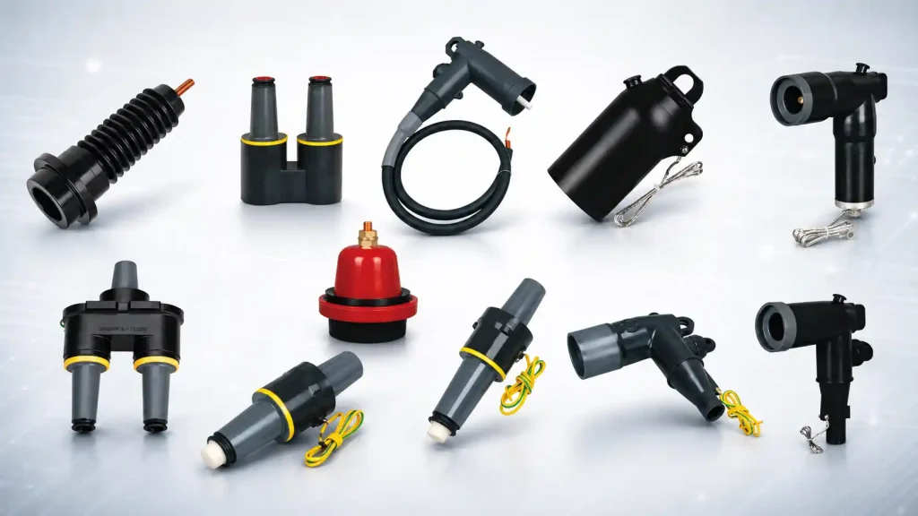
A 15kV Separable Connector creates an insulated and screened connection between a medium voltage cable and equipment such as switchgear, a ring main unit, transformer, compact substation, or cable branch box.
The Separable Connector uses a plug-in structure that supports installation, testing, maintenance, circuit extension, and equipment replacement. A complete system may also include bushing inserts, casing seats, loadbreak junctions, grounding elbows, insulation caps, and surge arresters. These components should be selected as a coordinated group of Medium Voltage Cable Accessories.
1. What Is a 15kV Separable Connector and How Does It Work?
A 15kV Separable Connector normally combines a conductor contact, molded insulation, stress-control section, external conductive shield, grounding point, and standardized plug-in interface.
Conductive connection
The internal contact transfers current between the cable conductor and equipment bushing. The performance of the Separable Connector depends on the correct conductor size, compression connector, crimping die, crimping sequence, and contact engagement.
Incorrect compression or an incomplete connection may increase resistance and cause localized heating.
Insulation and stress control
The insulation body of a Separable Connector isolates energized components and manages the electric field around the cable screen cutback. Accurate preparation dimensions help prevent excessive electrical stress.
The cable insulation should remain smooth, clean, and free from deep scratches. Conductive particles, moisture, and uneven semiconductive screen edges can reduce dielectric reliability.
Screening and grounding
The external conductive layer creates a screened surface when correctly grounded. The cable screen, accessory shield, grounding lead, and equipment earth point should form a continuous grounding path.
Plug-in interface
The plug-in interface mates with a compatible bushing insert, casing seat, loadbreak junction, or equipment bushing. For this reason, a Separable Connector cannot be selected from voltage and current markings alone. Interface profile, dimensions, and operating function must also match.
| Main component | Function | Selection or installation focus |
| Conductor contact | Transfers operating current | Conductor size and crimping method |
| Insulation body | Provides dielectric insulation | Voltage class and surface condition |
| Stress-control section | Controls the electric field | Cable preparation dimensions |
| Conductive shield | Maintains a screened surface | Grounding continuity |
| Plug-in interface | Connects with equipment | Interface type and dimensions |
| Operating eye | Supports approved operation | Loadbreak or deadbreak function |
| Test point, if fitted | Supports voltage detection | Compatible testing equipment |
2. Where Is a 15kV Separable Connector Commonly Used?
The compact and screened construction of a Separable Connector is suitable for systems where installation space, environmental protection, and maintenance access are important.
Ring main units and switchgear
A Separable Connector links incoming, outgoing, and transformer feeder cables to compatible bushings in ring main units and switchgear. It supports circuit isolation, cable testing, equipment replacement, and network reconfiguration.
The installed bushing interface, cable dimensions, feeder current, and operating function must be verified before selection.
Distribution transformers
A 15kV Separable Connector can connect a medium voltage cable to a compatible transformer bushing insert. This arrangement provides a compact, screened interface and simplifies planned transformer replacement.
Where surge protection is required, an elbow surge arrester may be integrated into the connection arrangement.
Compact substations and branch boxes
The screened Separable Connector helps reduce exposed clearances inside compact substations. Loadbreak junctions and multi-way accessories can also divide, combine, or extend feeder circuits in cable branch boxes.
Unused interfaces should be closed with correctly rated insulation caps rather than temporary covers.
Underground cable networks
A Separable Connector encloses the electrical interface in underground distribution systems where moisture, contamination, and restricted access may be present.
The connection remains dependent on correct sealing, clean mating surfaces, accurate cable preparation, and full interface engagement.
3. How Should a 15kV Separable Connector Be Selected?
A suitable Separable Connector should be chosen from verified system, cable, and equipment information rather than the product model alone.
Confirm the voltage class
A Separable Connector must match the nominal voltage, highest system voltage, insulation level, network grounding arrangement, and applicable project standard.
A 24kV product should not automatically be used in a 15kV system. Products with the same 200A rating may still have different interface dimensions and insulation requirements.
Check the continuous current
The Separable Connector should support the normal operating current, expected load variation, ambient temperature, and future expansion.
Many American-style interfaces are rated at 200A. Cable capacity, enclosure temperature, ventilation, contact resistance, and nearby heat sources should also be considered.
Match the cable specification
Each Separable Connector must fit the cable conductor size and actual insulation diameter. Required cable information includes:
- Copper or aluminium conductor
- Conductor cross-sectional area
- XLPE or other insulation material
- Actual insulation diameter
- Semiconductive screen construction
- Metallic shield type
- Cable outer diameter
The insulation diameter is particularly important because it affects accessory fit, stress control, and sealing.
Verify the equipment interface
A Separable Connector may connect to an equipment bushing, bushing insert, casing seat, loadbreak junction, or another compatible accessory.
Two products marked 15kV and 200A are not necessarily interchangeable. The interface profile, contact arrangement, operating function, and manufacturer documentation should agree.
Evaluate operating conditions
Loadbreak and deadbreak designs have different operating requirements. A connection should only be operated under load when it is specifically rated for this function and used with approved tools and procedures.
Environmental factors such as moisture, heat, dust, altitude, contamination, cable bending radius, and available operating space should also be reviewed.
| Selection factor | Information to verify | Main risk if incorrect |
| System voltage | Nominal and highest system voltage | Insufficient insulation level |
| Rated current | Continuous load and future demand | Overheating |
| Conductor | Material and cross-sectional area | Incorrect compression connection |
| Insulation diameter | Actual measured cable dimension | Poor fit and stress control |
| Equipment interface | Bushing and interface type | Incompatible connection |
| Operating function | Loadbreak or deadbreak | Unsafe operation |
| Environment | Moisture, heat, dust and altitude | Accelerated deterioration |
| Installation space | Cable bending and tool access | Mechanical stress |
| Accessory system | Junctions, caps and grounding | Incomplete coordination |
4. Which Medium Voltage Cable Accessories Complete the System?
The Separable Connector normally operates with several Medium Voltage Cable Accessories that provide connection, branching, grounding, insulation, interface extension, or surge protection.
Loadbreak elbow connectors and bushing inserts
The elbow is terminated on the cable, while the bushing insert creates the equipment interface. The Separable Connector system may use:
- JY ZT-15/200 15kV 200A Loadbreak Elbow Connector
- JY DTT-15/200 15kV 200A Bushing Insert
The JY ZT-25/200A Loadbreak Elbow Connector belongs to another voltage direction and should not be considered interchangeable without technical confirmation.
Casing seats and interface connectors
Casing accessories support equipment connection, interface extension, and feeder arrangement. Relevant product directions include:
- JY TGZ-200 15kV/24kV 200A Casing Seat
- JY STT-15/200 15kV 200A Double-Pass Casing Connector
- JY JCTGZ 15/200 15kV 200A Lengthening Casing
- JY DTT-24/200 24kV 200A Single-Pass Casing Joint
Each Separable Connector and casing accessory should be checked for voltage class, interface dimensions, and system compatibility.
Loadbreak junctions
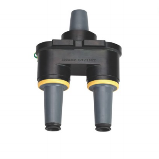
The JY MP-15kV 200A Loadbreak Junction provides connection points for feeder branching, cable extension, or circuit arrangement. The number of ways, current path, mounting position, and phase layout should follow the network design.
Grounding elbows and insulation caps
The JY JDZT-15/200 15kV 200A Grounding Elbow supports circuit grounding during an approved isolation procedure.
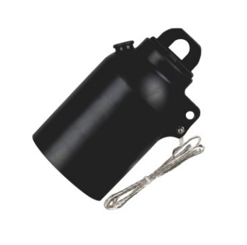
The JY JYM 15kV 200A American Type Insulation Cap protects an unused compatible interface from moisture, contamination, and accidental contact. The selected Separable Connector, grounding elbow, and insulation cap should belong to a coordinated interface system.
Elbow surge arresters
The JY BLQ-17/50 Elbow Surge Arrester can provide overvoltage protection at an appropriate cable interface. Its suitability depends on system grounding, operating voltage, temporary overvoltage conditions, and insulation coordination.
5. How Can Separable Connector Installation Improve System Reliability?
A Separable Connector can only achieve its intended performance when cable preparation, conductor compression, interface assembly, and grounding are properly controlled.
Prepare the cable accurately
The sheath, metallic screen, semiconductive layer, insulation, and conductor should be prepared to the specified dimensions. The Separable Connector should not be installed over insulation with deep scratches, moisture, conductive debris, or uneven screen edges.
Suitable stripping, shaving, measuring, cleaning, and crimping tools help maintain consistent installation quality.
Use the correct crimping method
The conductor connector, crimping die, sequence, and number of crimps should match the cable specification. The completed compression should be checked for sharp edges, incorrect positioning, and incomplete deformation.
Keep the interface clean
Before a Separable Connector is assembled, all mating surfaces should be clean and undamaged. Only the recommended lubricant should be applied.
If the components cannot be fully engaged, technicians should recheck the interface type, cable dimensions, component condition, and installation sequence. Excessive force should not be used to compensate for incompatibility.
Maintain grounding continuity
The cable screen, external conductive shield, grounding lead, equipment earth point, and surge protection grounding should form a continuous path.
Loose or missing grounding connections should be corrected before energization.
Inspect before operation
Pre-energization checks should cover:
- Correct product and phase identification
- Full interface engagement
- Cable support and bending radius
- Grounding continuity
- Insulation surface condition
- Closure of unused interfaces
- Compatibility of connected accessories
Electrical testing should follow the cable system requirements and the limitations of connected equipment.
Plan inspection and maintenance
Every disconnected Separable Connector should be inspected before reuse. Components showing damage, contamination, electrical tracking, deformation, or signs of overheating should be replaced.
Periodic inspection can also identify loose grounding leads, cable movement, corrosion, surface contamination, and abnormal temperature.
Conclusion
A 15kV Separable Connector provides a compact, screened, and maintainable connection between medium voltage cables and transformers, ring main units, switchgear, compact substations, and cable branch equipment.
Reliable performance requires correct system voltage, current rating, cable dimensions, equipment interface, operating function, and installation quality. Related Medium Voltage Cable Accessories should be selected as one coordinated connection system.
YIEOU supplies Separable Connector products and 15kV 200A American-style cable accessories for connection, branching, grounding, interface extension, insulation, and surge protection. Matching each component to verified cable and equipment data supports a safer and more reliable medium voltage network.