I. Product Overview
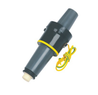
JY DTT-24/200 24kV 200A Single-pass casing joints are detachable cable conduit connection accessories specifically designed for 24kV (20kV level) medium-voltage power distribution systems. They feature a fully insulated, fully sealed, and touch-accessible structure, making them key components for 24kV ring main units, prefabricated substations, cable branch boxes, and other equipment. These joints achieve insulated connections between cables and equipment conduits and can be used with elbow-type cable joints, surge arresters, grounding devices, etc., to build a safe and reliable medium-voltage power distribution system interface. They also provide grounding protection and insulation isolation functions and are widely used in urban power grids, industrial power distribution, and new energy power distribution scenarios.
II. Product Characteristics
1. Electrical and insulation properties
- Made of high-purity EPDM ethylene propylene diene monomer rubber through integral injection molding, it has no seams or air gaps, excellent insulation performance, can withstand the rated voltage of 24kV system and short-time overvoltage, meets the operating requirements of the 24kV system’s highest operating voltage of 24kV, and has sufficient insulation margin.
- With an internal electric field optimization structure and stress control layer, the electric field is evenly distributed, effectively suppressing partial discharge. There is no risk of electrical erosion or breakdown during long-term operation, and the partial discharge amount is ≤10pC (1.5U₀).
- It comes with a grounding lead, which can achieve reliable grounding, effectively release fault current and induced voltage, and can be equipped with a live display device to intuitively monitor the live status and eliminate the risk of misoperation.
- The conductive contact parts are made of copper-tin plated, which has excellent conductivity, low contact resistance, low heat generation during long-term operation, and strong corrosion and oxidation resistance.
2. Structural and Safety Features
- With a fully insulated, fully sealed, and touch-accessible structure, the outer layer has high insulation strength, allowing direct contact with the outer casing during operation without the risk of electric shock, thus ensuring the safety of maintenance personnel.
- The single-channel integrated design is compatible with standard American/European 24kV equipment bushing interfaces. It has a compact structure, is easy to install, and can be directly inserted into the equipment bushing. It can be used with elbow cable joints, surge arresters, etc. to build a complete power distribution interface system.
- The anti-misconnection design features standardized interface dimensions, ensuring compatibility only with accessories of the corresponding specifications and eliminating the risk of incorrect connection. It also has a built-in positioning structure that locks in place after installation to prevent loosening or falling off.
- The grounding lead-out line uses a yellow-green special grounding wire, which is firmly connected and can be directly connected to the grounding grid, ensuring reliable grounding.
3. Environmental and Weather Resistance
- It has excellent weather resistance and can adapt to a wide temperature range of -40℃ to +90℃. The elasticity and insulation properties of the rubber do not decrease under high and low temperatures, and there is no risk of cracking or embrittlement. It is suitable for various outdoor and indoor scenarios.
- Moisture-proof, waterproof, stain-proof, and salt spray-proof, with an IP67 protection rating, it can operate stably for a long time in harsh environments such as underground, humid, and dusty conditions, and is not afraid of rain or condensation corrosion.
- It is resistant to aging, ultraviolet rays, and ozone corrosion, with a service life of over 30 years. It requires no maintenance and reduces subsequent operation and maintenance costs.
4. Mechanical and Adaptation Characteristics
- It has high mechanical strength, is impact and vibration resistant, and can withstand mechanical stress during transportation, installation and operation without deformation or damage risk. Its seismic resistance level reaches level 8.
- It is compatible with 24kV 200A standard equipment bushing interfaces and can be interchanged with elbow-type cable joints, surge arresters, and grounding devices of the same specifications, making it highly versatile.
- The interface is standardized and conforms to IEEE 386 and relevant domestic standards, and can be adapted to the equipment bushings of mainstream 24kV ring main units, prefabricated substations, and cable branch boxes.
III. Technical Parameters
| Parameter categories | project | Technical indicators |
| Rated electrical parameters | Rated voltage (Ue) | 24kV (Applicable to 20kV systems, maximum operating voltage 24kV) |
| Rated current (Ie) | 200A | |
| Rated frequency (fn) | 50Hz/60Hz | |
| Power frequency withstand voltage | 65kV/5min (dry test), 55kV/5min (wet test), no breakdown, no flashover. | |
| Lightning impulse withstand voltage | 125kV (peak value), no breakdown, no flashover | |
| Partial discharge quantity | ≤10pC (below 1.5U₀) | |
| Rated short-circuit withstand current | 16kA/2s (20kA/2s optional, depending on system requirements) | |
| Contact resistance | ≤100μΩ | |
| Structural and material parameters | Main material | EPDM (ethylene propylene diene monomer) rubber (insulating layer), tin-plated copper (conductive contacts) |
| Protection level | IP67 | |
| Interface Standard | 24kV American standard bushing connection (compatible with European connections of the same specification) | |
| grounding method | It comes with a yellow-green bicolor grounding lead for direct grounding. | |
| Environmental parameters | Applicable altitude | ≤2000m (Customization available for high altitudes) |
| Ambient temperature | -40℃/ +90℃ (operating temperature), -40℃/ +70℃ (storage temperature) | |
| relative humidity | ≤100% (no condensation) | |
| Seismic resistance level | Level 8 | |
| Implementation Standards | IEEE 386, GB/T 12706, DL/T 404, GB/T 11022 |
IV. Scope of Application
- Applicable voltage levels : 20kV~24kV AC medium voltage power distribution systems, compatible with equipment bushing interfaces with a maximum operating voltage of 24kV.
- Applicable equipment scenarios :
- Bushing interface connection for power distribution equipment such as 24kV ring main units, prefabricated substations, cable branch boxes, and American-style prefabricated substations;
- Used in conjunction with elbow-type cable joints, surge arresters, and grounding devices to construct detachable cable terminals and surge arrester interfaces;
- Urban power distribution network cable lines, power distribution systems of industrial and mining enterprises, and power distribution interfaces for new energy (photovoltaic/wind power) booster stations;
- Insulation connection of equipment sleeves in various scenarios such as indoor/outdoor power distribution rooms, underground pipe corridors, and cable tunnels.
- Function and Purpose : To achieve the insulated and sealed connection between equipment bushings and cable accessories, and to provide grounding protection and insulation isolation functions, providing a safe and reliable interface solution for power distribution systems.
V. Usage Conditions
1. Normal operating conditions
- Altitude: ≤2000m;
- Ambient temperature: -40℃~+90℃; equipment operating temperature complies with relevant standards.
- Relative humidity: ≤100% (no condensation);
- Environmental conditions: No corrosive gases, no flammable or explosive media, no severe vibration or impact;
- Installation method: It is compatible with standard equipment sleeve interfaces and can be installed horizontally or vertically. The installation space must meet the operation requirements of the accessories.
2. Special usage conditions (customization required)
- The altitude exceeds 2000m;
- The ambient temperature exceeds the range of -40℃ to +90℃;
- Severely polluted, salt spray, and chemically corrosive environments;
- High vibration and high impact conditions;
- Non-standard equipment sleeve interface specifications;
- Special grounding requirements and high pollution levels.
VI. Installation and Maintenance
1. Installation Requirements
- Before installation, inspect the product appearance for cracks, damage, bubbles, and undamaged insulation surfaces; check that the grounding lead is intact and free of rust, and that all accessories are complete.
- Clean the surface of the equipment sleeve interface to remove oil, dust, and foreign objects, ensuring the interface is dry and clean.
- Apply a special silicone grease lubricant evenly to the inner wall of the bushing joint to avoid damaging the insulation layer during installation.
- Slowly push the connector into the equipment sleeve interface to ensure it is fully in place, lock the positioning structure, and connect the grounding lead to the grounding grid. The grounding resistance should be ≤4Ω.
- After installation, insulation resistance and power frequency withstand voltage tests are conducted. Only after passing these tests can the equipment be put into operation.
2. Maintenance Requirements
- Regularly inspect the appearance of the connectors, ensuring there are no cracks, discharge marks, or dirt accumulation, and that the grounding lead is securely connected without any looseness.
- Regularly test the insulation resistance to ensure that the performance meets the requirements and to detect potential faults in a timely manner.
- Clean the surface of the connector to remove dust and dirt, and keep the insulation surface dry and clean to avoid corrosion from oil and chemicals.
- If any abnormalities such as cracks, damage, discharge, or overheating occur in the connector, it must be stopped immediately and replaced. Operation with defects is strictly prohibited.
- Special insulated tools must be used for plugging and unplugging of accessories (such as elbow joints and surge arresters). It is strictly forbidden to operate live joints by hand. Power distribution safety regulations must be strictly followed during operation.
VII. Precautions
- The product must be installed, debugged, and maintained by professional electrical personnel with medium-voltage power distribution construction qualifications. Operation by non-professional personnel is strictly prohibited.
- The product must be used in conjunction with the corresponding specifications of equipment bushings, elbow cable joints, surge arresters, etc. It is strictly forbidden to use the wrong specifications of interfaces, otherwise it will lead to insulation failure and safety accidents.
- The connector must not be disassembled or modified without authorization, otherwise the warranty and safety guarantee will be lost. It is strictly forbidden to use non-special tools to forcibly install or disassemble the connector.
- When storing, it should be placed in a dry, ventilated, and cool environment, avoiding direct sunlight, high temperature, humidity, and compression. It is strictly forbidden to contact with sharp objects that may damage the insulation layer.
- When operating accessories on live circuits, it is essential to strictly adhere to power distribution safety regulations, implement appropriate safety precautions, and strictly prohibit any unauthorized operations.
VIII. Model Description
| Model Identification | meaning |
| JY | Product series code |
| DTT | Single-pass sleeve fitting series code |
| twenty four | Rated voltage rating, compatible with 24kV systems, maximum operating voltage 24kV |
| 200 | Rated current rating, compatible with 200A current rating |
| Single-pass casing joints | Single-through bushing fitting, used as an insulating connection accessory for equipment bushing interfaces. |
IX. Implementation Standards and Certification
- International Standard: IEEE 386 “Medium Voltage Detachable Cable Connector Standard”;
- National standards: GB/T 12706 “Extruded insulated power cables and accessories with rated voltage of 1kV (Um=1.2kV) to 35kV (Um=40.5kV)”, GB/T 11022 “Common technical requirements for high voltage switchgear and controlgear standards”, DL/T 404 “3.6kV~40.5kV AC metal-enclosed switchgear and controlgear”;
- The product has passed the type test of the National High Voltage Electrical Apparatus Quality Supervision and Inspection Center and meets national electrical safety standards.
X. After-sales service
- Product warranty period: 18 months from the date of manufacture, or 12 months from the date of commissioning (whichever comes first).
- During the warranty period, products will be repaired or replaced free of charge if quality issues arise.
- We provide technical support, installation guidance, and customized services (adaptation to special specifications and working conditions).
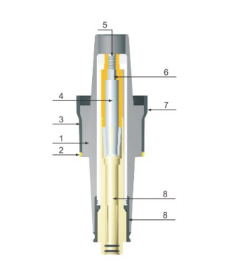
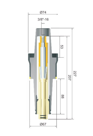
Appendix: Product outline diagram