
Selecting a T-Body Connector for a Ring Main Unit (RMU) involves more than matching the voltage and current ratings printed on a product specification. The connector also needs to fit the RMU bushing interface, medium-voltage cable dimensions, conductor type, installation layout, and the overall connection arrangement inside the cable compartment.
For RMUs using European-style screened separable connections, the equipment interface is usually one of the first details we look at. A Type C bushing interface commonly used on medium-voltage equipment, for example, needs a corresponding T-Body Connector designed for that interface. From there, cable conductor size, diameter over insulation, system voltage, rated current, and available installation space help determine the complete connector configuration.
At YIEOU, we manufacture medium-voltage cable accessories for RMUs, switchgear, transformers, compact substations, cable branch equipment, and other power distribution applications. When matching a T-Body Connector for an RMU project, we consider the connector together with the cable and equipment interface so that the complete connection works as one system.
Start with the RMU Bushing Interface
The RMU bushing is usually the best place to begin.
Once an RMU has been selected, its equipment interface is already defined. The T-Body Connector therefore needs to match that interface before other details such as cable adapter size or conductor contact are finalized.
This matters because T-shaped connectors can look very similar from the outside while using different mating dimensions and connection structures.
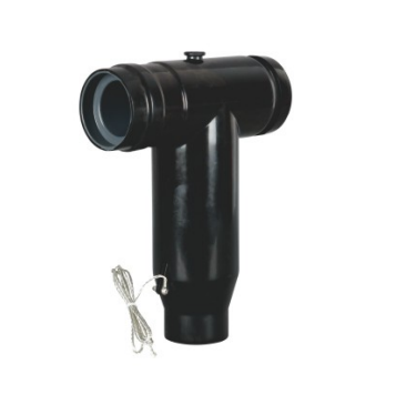
For many European-style medium-voltage RMUs and switchgear systems, Type C interfaces in accordance with EN50181 are commonly used with screened separable connectors.
EN50181 covers plug-in type bushings used on medium-voltage equipment other than liquid-filled transformers and provides standardized interface dimensions that allow suitable separable connectors to be matched with the equipment bushing.
What we usually check on the RMU side
For a new RMU project, useful information normally includes:
- RMU model;
- rated voltage;
- rated current;
- bushing type;
- interface designation;
- cable compartment layout;
- and equipment drawings where available.
For an existing installation, the bushing marking and existing connector model can also help identify the required configuration.
Clear photographs are useful when replacing an existing connector, although equipment markings and dimensional information provide a more reliable basis when the interface cannot be identified from the product model alone.
The objective is simple: the connector selected for the cable should correspond to the actual interface already provided on the RMU.
Keep the Connector Interface Consistent with the Equipment
YIEOU manufactures both European-style and American-style medium-voltage cable accessories, and each system has its own interface characteristics.
Our European-type cable accessories are developed around commonly used DIN and EN interface requirements, including EN50181 for relevant equipment connections. Our American-type separable connector products are designed around ANSI/IEEE386 interface systems.
Both product families are widely used in medium-voltage distribution, but they serve different equipment designs.
This becomes particularly relevant when project documents contain ratings such as 600A or 630A.
600A and 630A connectors may belong to different connection systems
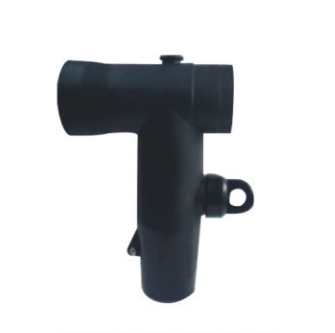
A 600A separable connector is commonly found in American-style medium-voltage distribution equipment, while 630A ratings are frequently seen in European-style screened connector systems.
The difference is therefore not simply the small difference in rated current.
The two products may also differ in:
- equipment bushing interface;
- connector dimensions;
- applicable standard;
- contact arrangement;
- installation method;
- and compatible accessories.
For an RMU using a European-style Type C interface, we would normally select the T-Body Connector within the corresponding European connector system. If the equipment uses an ANSI/IEEE interface, the accessory configuration follows that system instead.
Looking at the interface together with the current rating makes the selection much clearer than comparing the 600A and 630A figures on their own.
Match the Voltage Rating to the RMU and Cable System
Once the equipment interface is clear, the voltage class can be matched.
RMUs are used across different medium-voltage distribution systems, so T-Body Connectors are also available in different voltage ranges.
Depending on the project, the equipment may be designed for systems such as:
- 12kV;
- 17.5kV;
- 24kV;
- 36kV;
- or another specified medium-voltage class.
The connector rating needs to correspond with the RMU, cable insulation system, and overall project requirements.
Voltage class affects the complete connector design
Voltage rating influences more than the insulation marking on the product.
It can also affect:
- connector body dimensions;
- insulation thickness;
- electric-field control;
- cable adapter dimensions;
- compatible cable insulation diameter;
- equipment interface;
- and electrical test requirements.
This is particularly relevant inside compact RMU cable compartments.
As the voltage class and cable dimensions increase, the connector and cable arrangement may require more installation space. The available compartment depth and cable bending area therefore become part of the selection as well.
For example, when working with a 24kV RMU using a defined Type C interface, we first identify the connector system that matches the equipment and then select the cable components within the appropriate dimensional range.
Rated Current Should Match the Actual RMU Circuit
The required current rating depends on how the RMU circuit is being used.
An RMU may include:
- incoming feeders;
- outgoing feeders;
- transformer feeders;
- bus connections;
- or other distribution circuits.
Each circuit can have different operating requirements.
For a T-Body Connector connection, the current rating of the connector needs to work together with the RMU bushing, cable conductor, and internal conductor contact.
The current rating is one part of the specification
A description such as:
630A T-Body Connector
already tells us something useful, but several other details are still needed before the exact configuration becomes clear.
For example:
- Is the system 12kV, 24kV, or another voltage class?
- Which bushing interface does the RMU use?
- What is the cable conductor size?
- What is the actual diameter over insulation?
- Is the conductor copper or aluminium?
- Does each phase use one cable or an additional rear connection?
Once these details are known, the rated current fits naturally into the complete selection.
This approach is especially useful for RMUs because their cable compartments are compact and normally leave limited room for changing the connector arrangement after the equipment has already been installed.
Cable Cross-Section Is Only the Starting Point
Cable size is another key part of T-Body Connector selection.
Specifications such as 120mm², 240mm², or 300mm² provide important conductor information, but the conductor cross-section alone does not describe the complete cable geometry.
Check the actual diameter over insulation
Two medium-voltage cables with the same conductor cross-section can have different insulation dimensions.
The difference may come from:
- cable manufacturer;
- conductor construction;
- voltage class;
- insulation thickness;
- conductor screen;
- insulation screen;
- or cable standard.
The cable adapter and stress-control section inside the T-Body Connector need to match the actual cable dimensions.
For this reason, diameter over insulation is one of the measurements we normally confirm when matching a connector.
For example, two 240mm² cables may use different cable adapter sizes even though their nominal conductor cross-sections are the same.
That is why a cable datasheet is often more useful than the conductor size alone.
Conductor material also affects the internal connection
The cable conductor may be copper or aluminium.
This information needs to match the conductor contact or mechanical lug used inside the T-body.
Where shear-bolt or mechanical contacts are used, their conductor range also needs to cover the actual cable conductor.
By checking the conductor, cable adapter, connector body, and RMU bushing together, the connection can be prepared as one coordinated assembly rather than having individual components selected separately.
Installation Space Inside the RMU Matters
An electrically correct T-Body Connector also needs to fit comfortably inside the RMU cable compartment.
RMUs are compact by design, and this can make cable routing an important part of the connector selection.
In many installations, medium-voltage cables enter the RMU from below and then rise toward the equipment bushings.
The available space needs to accommodate both the connector and the natural bending of the cable.
Cable entry and bending space
A large medium-voltage cable can be relatively stiff.
If the RMU bushing sits close to the bottom of the compartment or the cable trench is shallow, the cable may have to turn within a limited distance.
A practical layout therefore considers:
- bushing height;
- cable entry position;
- cable diameter;
- trench depth;
- cable bending space;
- and cable support points.
The cable should be able to reach the connector without the connector itself having to hold the cable under excessive mechanical force.
Larger cables can change the whole compartment layout
As cable size increases, installation becomes more demanding.
Three large cables installed side by side need enough room for cable preparation, connector assembly, grounding, and final inspection.
The installer also needs access to:
- prepare the cable insulation;
- install the stress-control components;
- connect the conductor;
- position the T-body;
- tighten the connection;
- install the rear insulating components;
- and complete the grounding connection.
For compact RMUs or larger cable sizes, reviewing the cable compartment drawing before finalizing the accessory configuration can prevent installation difficulties later.
Choose the Connection Arrangement Around the Actual RMU Design
Not every RMU uses exactly the same T-Body Connector arrangement.
Some applications require a single cable connection at each phase. Others may need an additional connection behind the front T-body.
The connector configuration should reflect the actual circuit arrangement.
Single-cable connection
In a straightforward feeder arrangement, one T-Body Connector connects the medium-voltage cable to the RMU bushing.
The rear section of the connector is then completed with the components required by that connector design.
This arrangement is commonly used when each RMU bushing serves one cable circuit.
Front and rear connector arrangements
Certain projects require another compatible connector or accessory behind the first T-body.
Depending on the system, this arrangement can support:
- an additional cable;
- another circuit connection;
- surge protection;
- or another compatible accessory.
This configuration affects both the connector components and the available space inside the RMU.
When a front-and-rear arrangement is planned, we look at:
- connector compatibility;
- connecting stud arrangement;
- compartment depth;
- cable routing;
- grounding;
- and working clearance.
Confirming this during the initial selection is much easier than trying to add another connection after the RMU and cables are already in place.
Screening, Stress Control, and Grounding Work Together
A T-Body Connector does more than carry current from the cable conductor into the RMU.
It also forms part of the insulation, screening, and electric-field control system at the end of the medium-voltage cable.
A screened T-Body Connector typically combines:
- conductor connection;
- insulation;
- electric-field control;
- external conductive screening;
- and grounding.
These functions are closely related.
Cable preparation affects stress control
During installation, part of the cable insulation screen is removed so that the connector can be fitted.
This creates a transition between the screened cable and the connector interface.
The stress-control section of the accessory manages the electric field around this transition.
Correct cable dimensions therefore matter not only for physical fit but also for the intended electrical performance of the connector system.
The cable adapter needs to match the diameter over insulation so that the stress-control structure sits in the correct position.
Grounding completes the screened connection
The external conductive layer of a screened T-Body Connector is connected to earth as part of the overall grounding arrangement.
The cable screen, connector screen, and RMU earthing system therefore need to be considered together.
In practice, this means that connector selection is closely connected with cable preparation and installation quality.
A well-matched connector system makes those installation steps much more straightforward.
T-Body Connectors and Loadbreak Elbows Serve Different Applications
T-Body Connectors are separable, but their operating role is different from that of a typical 200A loadbreak elbow.
This distinction is useful when choosing accessories for different types of medium-voltage equipment.
A 200A loadbreak elbow is designed around a connection system where loadbreak operation may form part of the product function.
Higher-current screened T-body connections commonly used on RMUs and switchgear are generally intended to provide a secure cable-to-equipment connection while the RMU itself performs the switching operation.
For an RMU application, this means the switch, circuit breaker, or other switching device inside the equipment handles circuit operation, while the T-Body Connector remains the cable interface.
When maintenance or cable disconnection is required, the connector is handled according to the operating procedure and ratings of the complete system after the relevant circuit has been isolated.
Keeping these two product applications separate also helps avoid selecting a connector simply because both products belong to the broader separable connector family.
What Information Helps Us Match an RMU T-Body Connector?
For most projects, a relatively small amount of accurate equipment and cable information is enough to narrow down the correct connector configuration.
| Information | Why It Matters |
| RMU rated voltage | Defines the required voltage class |
| RMU rated current | Helps establish the connector current range |
| Bushing interface | Determines the equipment-side connection |
| Interface system | Identifies the appropriate European or American connector family |
| Cable conductor size | Used to select the conductor contact |
| Conductor material | Confirms compatibility with copper or aluminium conductors |
| Diameter over insulation | Determines cable adapter sizing |
| Cable construction | Helps confirm accessory compatibility |
| Number of cables per phase | Defines the required connector arrangement |
| Cable entry direction | Affects installation layout |
| Cable compartment dimensions | Confirms connector and cable clearance |
| Grounding arrangement | Helps coordinate the screened connection |
An RMU cable compartment drawing and cable datasheet usually contain much of this information.
For a replacement project, the existing connector model, bushing marking, cable data, and clear installation photographs can also make identification easier.
How We Match T-Body Connectors for RMU Projects at YIEOU
At YIEOU, we look at an RMU connection as a combination of the equipment bushing, connector, cable adapter, conductor connection, cable, and grounding arrangement.
This is more useful than starting from a general description such as “24kV T-Body Connector” or “630A connector” and working backward.
Our medium-voltage cable accessory range includes European- and American-style separable connectors, cold-shrink cable accessories, surge protection products, cable branch equipment, and related connection components.
For European-style RMU projects, we match the connector to the corresponding equipment interface and cable dimensions. For projects using American-style equipment, the accessory system is selected around the applicable ANSI/IEEE interface.
Manufacturing and testing are part of the same process
A T-Body Connector combines conductive, insulating, stress-control, screening, and mechanical functions within one compact component.
Consistent manufacturing and electrical testing are therefore important parts of the product process.
Our manufacturing facilities include voltage-withstand testing, partial-discharge testing, electrical-performance testing, and material inspection capabilities for medium- and high-voltage cable accessories.
For an RMU project, our aim is to confirm the important matching details before production so that the connector supplied is already suited to:
- the RMU bushing;
- voltage and current requirements;
- cable dimensions;
- conductor material;
- installation space;
- and connection arrangement.
This makes the accessory easier to integrate into the actual equipment rather than leaving interface questions to be resolved during installation.
Conclusion
A suitable T-Body Connector for an RMU starts with understanding how the cable will connect to the actual equipment.
The RMU bushing interface establishes the equipment side of the connection. Voltage and current ratings then define the electrical requirements, while cable conductor size, diameter over insulation, and conductor material determine the cable-side components.
Installation space and connection arrangement are equally important, particularly in compact RMU cable compartments.
For a typical project, the main points to confirm are:
- RMU bushing interface;
- voltage and current rating;
- European or American connector system;
- cable conductor size and material;
- actual diameter over insulation;
- available cable bending and installation space;
- required front or front-and-rear connection;
- and grounding arrangement.
At YIEOU, we match these details together when preparing T-Body Connector solutions for RMU applications. By treating the cable, connector, and equipment interface as one connection system, the final configuration can fit the actual project more naturally and reduce unnecessary changes during installation.
FAQ
What is a T-Body Connector used for in an RMU?
A T-Body Connector provides a screened and insulated connection between a medium-voltage cable and the equipment bushing inside an RMU. Its structure is well suited to compact cable compartments where medium-voltage cables commonly enter from below.
What is a Type C interface on an RMU?
Type C is a standardized bushing interface commonly used with screened separable connectors on European-style medium-voltage equipment. EN50181 covers plug-in type bushings used on equipment such as RMUs and switchgear.
What is the difference between 600A and 630A T-Body Connector systems?
600A ratings are commonly associated with American-style separable connector systems, while 630A ratings are frequently used with European-style screened connector systems. The equipment interface and applicable standard are more important than comparing the two current values directly.
Is cable cross-section enough to select a T-Body Connector?
No. Cable conductor size is important, but the actual diameter over insulation, conductor material, cable construction, voltage class, and equipment bushing interface also affect the final connector configuration.
Can a T-Body Connector be disconnected while carrying load current?
A typical higher-current T-Body Connector used on an RMU is not selected to perform the switching function. The RMU switching device handles circuit operation, while connector disconnection is carried out according to the requirements of the specific system after the relevant circuit has been properly isolated.