
A replacement cable can arrive with the same voltage designation and conductor cross-section as the cable being removed, yet require a different termination kit. The difference may only become apparent when the insulation diameter, conductor construction or screen arrangement is compared with the original cable. On an existing transformer feeder, the equipment bushing and cable entry may remain exactly where they were. The new cable therefore has to fit an established connection arrangement. Selecting a Separable Connector for this work means checking what has changed on the cable side while preserving the requirements of the equipment side.
Quick Answer
A Separable Connector for a replacement medium-voltage cable must match the retained equipment bushing and the new cable specification. Keeping the same nominal conductor size does not establish compatibility. The diameter over insulation, conductor material and construction, contact selection, screen arrangement and available cable route can change even when the purchase description looks similar. Reusing the original connector model and reusing the original installed components are also separate decisions.
At YIEOU, we manufacture medium-voltage cable accessories and match connector assemblies to the cable and equipment used in each project. For existing American-style loadbreak systems, our JY ZT-15/200 elbow is designed for 15kV, 200A applications with a compatible equipment interface. When replacing an existing connector, however, the original part number alone is not enough to confirm suitability. The cable size, insulation diameter, conductor size, and equipment interface should also be checked before selecting the replacement.
Retain the Equipment Interface as the Starting Point
When the equipment remains in service, its bushing defines the connection that the new assembly must meet. Record the bushing identification, voltage class, current rating and interface drawing before comparing cable-side options. A photograph can help identify the installed arrangement, but it cannot establish every contact dimension or distinguish all versions of a similar-looking accessory.
The existing Separable Connector may have worked with a particular combination of elbow, insert and bushing well. Replacing the cable does not make those components interchangeable with another system. An insert that screws into a well has two interfaces to consider: the well connection and the exposed interface that mates with the elbow. Both remain relevant if an insert is replaced during the same outage.
Our JY DTT-15/200 is a 15kV, 200A bushing insert that threads into a compatible bushing well. It is an equipment-side component; it does not determine the acceptable insulation diameter of the replacement cable. That distinction helps separate a bushing replacement decision from the selection of the cable termination assembly.
For an existing deadbreak installation, preserve the documented deadbreak interface requirements. A new cable with greater current-carrying capacity does not justify changing to a different connector family. Likewise, a 600A and a 630A interface cannot be treated as equivalent because their current ratings are close. The retained bushing, specified connection system and matching dimensions decide the available options.
A Separable Connector chosen within the correct equipment family can then be matched to the new cable. This order of review avoids selecting an attractive cable-side kit that cannot connect to the equipment already on site.
Compare Insulation Diameter Before Repeating the Old Order
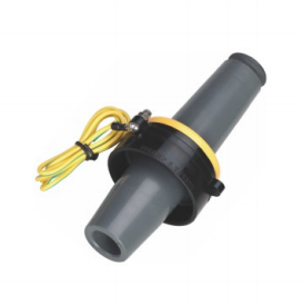
The conductor cross-section describes the conductive metal area. Diameter over insulation describes a different part of the cable: the outside diameter of the insulation at the mating area defined by the accessory instructions. Neither the overall jacket diameter nor a measurement taken over an additional layer is automatically an acceptable substitute.
Two cables with the same conductor area can have different insulation diameters because their conductor geometry, insulation design or specified voltage construction differs. A change of cable manufacturer can therefore affect the Separable Connector selection even when the conductor size on the order remains unchanged. The new cable datasheet needs to be compared with the accessory’s permitted fit range.
Consider a replacement feeder described as 120 mm². If that is the only information carried forward from the original order, the replacement Separable Connector kit has not yet been defined. The new cable’s insulation diameter could fall within the original kit’s approved range, require another cable adapter within the same Separable Connector family, or require a different assembly. These are possible selection outcomes, not interchangeable ways of making an unsuitable body fit.
The Separable Connector relies on its designed fit to establish the cable-side insulation interface. Excess clearance or excessive interference cannot be corrected by applying extra lubricant, adding improvised material or altering the body. A cable adapter is acceptable only when it is a specified part of the selected connector assembly.
Where cable dimensions are close to a kit boundary, the actual cable tolerance matters. Ask for the cable manufacturer’s dimensional range and follow the accessory manufacturer’s measurement requirements. A nominal catalogue diameter alone may not describe all delivered cable. We can review the available cable data with the proposed assembly before the replacement order is finalized.
Match the New Conductor to the Contact
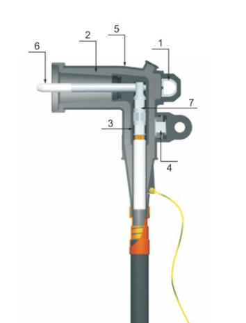
A cable replacement may change copper to aluminium, use a different strand construction or introduce a compacted conductor. These differences affect the contact even if the insulation still fits the same connector body. The contact must accommodate the conductor material, cross-section and construction using the connection method specified for that assembly.
For a Separable Connector with a compression contact, the approved contact and its installation tooling belong together. Matching the nominal conductor area is only part of the decision. The barrel dimensions, approved conductor type and specified compression method also matter. A contact that accepts the conductor physically has not necessarily established the intended electrical joint.
Where a connector family uses another contact method, such as a specified mechanical contact, its permitted conductor range and installation requirements still apply. A field substitution between contact designs can change the position of the connection inside the insulation body. It cannot be justified solely by the fact that both contacts are described for the same cable size.
The Separable Connector contact also has to reach the intended position after cable preparation. Reusing the old cutting dimensions with a different kit can leave the contact or stress-control region incorrectly located. The installation instruction supplied for the selected assembly is therefore part of the replacement specification, along with the contact identification.
It is useful to keep three details distinct on the order: the connector body or family, the cable fit designation and the conductor contact. Together they define the cable-side assembly more accurately than a single broad description such as a 200A elbow. We can use the new conductor details to review the relevant Separable Connector contact option without assuming that the old contact suits the new cable.
Treat Cable Changes According to the Part They Affect
Some cable changes affect one Separable Connector selection item; others affect several parts of the connection. Comparing the old and new cable specifications makes those differences visible before the installation team opens a kit. The following table summarizes the connection consequences rather than assigning an automatic replacement part.
Table 1. Cable changes and their connection implications
| Change in the replacement cable | Connection item affected | Selection consequence |
|---|---|---|
| Same conductor area but a different insulation diameter | Cable-side body fit or specified adapter | Recheck the permitted diameter range for the exact assembly. |
| Copper changed to aluminium or a different conductor construction | Conductor contact and installation method | Confirm the contact is approved for the new material and construction. |
| Larger conductor area | Contact, insulation fit and cable route | Review all three; a larger cable does not increase the bushing rating. |
| Different metallic screen or sheath construction | Screen connection and sealing accessories | Match the termination arrangement to the new cable construction. |
| Greater overall diameter or stiffness | Cable support and entry geometry | Confirm the assembly can align without sustained side loading. |
| Different voltage construction | Insulation coordination and cable dimensions | Recheck the complete connection against the system requirements. |
For the Separable Connector order, identify the changed item explicitly. If the cable material changes while the equipment and circuit duty remain the same, the review can concentrate on the contact and cable fit. If conductor size, insulation diameter and cable stiffness all change, a broader assembly and layout review is necessary.
This approach also helps an EPC contractor or distributor avoid repeating an incomplete historical description. An old invoice may name a connector family but omit the contact or adapter designation. The replacement cable specification provides the missing basis for selecting a complete kit.
A Different Cable Rating Does Not Upgrade the Connection
A higher cable voltage designation or larger conductor does not increase the rating of the retained bushing, contact or Separable Connector. The completed connection remains subject to the ratings and application limits of its actual components. A cable upgrade and a connection upgrade therefore require separate confirmation.
Our JY ZT-15/200 and JY ZT-25/200A are distinct loadbreak elbow product models, both rated at 200A within their respective Separable Connector voltage families. They illustrate why the current number alone cannot identify a replacement elbow. Selection depends on the documented voltage requirements and the matched equipment interface for the particular assembly.
For a replacement Separable Connector in an American-style system, relevant interface requirements may be specified through IEEE 386. The applicable edition and interface designation need to agree with the equipment and accessory documentation. A reference to the standard does not, by itself, establish that every connector carrying that reference can mate with every bushing.
The operating function also stays with the specified connection system. A loadbreak accessory supports only its rated operations in a compatible assembly under the prescribed procedure. A deadbreak accessory provides a connection that is separated under the required de-energized conditions; it does not become a load switch when fitted to a new cable.
Replacement planning benefits from keeping those duties clear. If the project now requires a different operating method, that is a change to the equipment connection specification. It requires review of the full matched arrangement, rather than substitution of one cable accessory during installation.
Check the Cable Route in the Existing Compartment
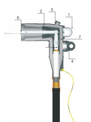
The Separable Connector can satisfy electrical and cable-fit requirements yet be difficult to install because the replacement cable approaches it at a different angle. A larger jacket diameter, different armour or greater stiffness can affect the bend and support arrangement inside an existing transformer or cable connection enclosure.
The available space includes more than the envelope occupied by the installed Separable Connector body. The cable needs sufficient length for the specified preparation, the required bending radius and alignment with the bushing. The assembly also needs the access specified for fitting and later removal. A route that forces the cable against the cabinet wall may transfer sustained side load into the connection.
When replacing a damaged cable end, the remaining usable length deserves particular attention. Removing the damaged section can shorten the cable enough to change how it reaches the bushing. The new Separable Connector cannot compensate for a cable that no longer reaches the intended position without excessive strain. The route, support or repair arrangement needs to be reviewed before the kit is installed.
Screen and sheath details can change the space needed around the cable entrance as well. A different metallic screen arrangement may require different connection hardware or routing of the earth lead. Sealing accessories need to suit the actual sheath and installation environment. These items are part of the termination arrangement even though they are not the main connector body.
For replacement work, an equipment drawing accompanied by cable-entry dimensions can resolve questions that a close-up product photograph cannot. We can review our cable accessory dimensions against the proposed arrangement while the project team confirms the cable bend, support and available working space.
Separate Model Reuse from Component Reuse
If the new cable matches all requirements of the existing Separable Connector model, a new Separable Connector kit of that model may remain suitable. That conclusion does not automatically permit reuse of the previously installed body, contact or other components. Each has a different condition and replacement question.
A compression contact already attached to the removed conductor is not equivalent to a new contact selected for the replacement cable. Similarly, a connector body may have experienced heat, contamination, mechanical damage or deterioration that is not captured by its original model number. The product instructions and condition assessment determine which components, if any, may remain in service.
The retained bushing also needs its own review. Damage at a contact or mating surface can affect the new assembly even if the new cable and elbow are correctly selected. Replacing only the cable-side Separable Connector does not resolve a defective equipment-side interface. Where the connection has failed, the cause needs to be understood sufficiently to identify the affected components.
Keep the work within the approved outage, isolation, testing and earthing arrangements for the equipment. A detachable design does not establish that the circuit is safe to handle. Installation and return-to-service checks belong to qualified personnel following the applicable equipment, cable and accessory instructions.
The practical outcome is a clearly defined replacement scope: components being retained, new parts being supplied and the instructions applicable to the assembled connection. This makes the order more useful to the installation team than a general request to replace the old elbow.
Confirm a Complete Replacement Assembly
A useful starting package is the new cable datasheet, the existing connector and bushing identification, and the equipment connection drawing. Where drawings are unavailable, clear markings, photographs and cable-entry dimensions can help us identify what still needs confirmation. Complete information is helpful, but an initial enquiry can begin with the details already available.
For the Separable Connector quotation, the final description can identify the chosen Separable Connector body, cable fit designation, conductor contact and required installation accessories. Any retained equipment-side component should be identified separately. This allows the replacement kit to be checked against the actual new cable rather than against a shortened description from an earlier purchase.
At YIEOU, we provide technical support for matching replacement cable assemblies within our medium-voltage accessory range. Once the equipment interface and cable details are established, we can review the relevant product direction and required assembly information. For repeated replacement orders, retaining the confirmed cable designation and kit details helps distinguish a true repeat order from a later cable substitution.
The right Separable Connector selection preserves the equipment interface while accommodating the cable that will actually be installed. At YIEOU, we can help review that connection so the replacement order reflects the new cable, the retained equipment and the available installation space.
FAQ
Can the same Separable Connector model fit a replacement cable of the same size?
Possibly, but the conductor cross-section alone is insufficient. Confirm insulation diameter, conductor material and construction, contact selection and the equipment interface against the exact kit requirements.
Which cable diameter matters for the connector body?
Use the diameter at the cable layer and location specified in the accessory instructions, normally the relevant diameter over insulation. Overall jacket diameter is a separate dimension and cannot automatically replace it.
Does a larger cable increase the current rating of the connection?
No. The Separable Connector, contact, bushing and other components retain their own ratings. A larger conductor may also require a different contact, cable fit designation or installation route.
Can a cable adapter correct any insulation diameter mismatch?
No. An adapter is suitable only when it is a specified part of the selected assembly and covers the actual cable dimensions. Improvised packing or modification of the connector body does not establish compatibility.
Must the bushing insert be replaced with the cable?
Not automatically. Its compatibility, condition and the applicable maintenance instructions determine whether it can remain. A damaged or unsuitable bushing interface needs to be addressed separately from cable-side kit selection.
What information helps YIEOU review a replacement order?
The new cable datasheet, insulation diameter, conductor details and existing bushing identification are particularly useful. An equipment drawing or photographs with cable-entry dimensions help us review the physical arrangement and identify any information still needed.