
A warm cable compartment does not automatically mean that a connector is defective. Medium-voltage cables, bushings, contacts, and nearby equipment all carry load and release heat. The useful question is whether one connection is behaving differently from comparable phases or from its own previous condition. A localized rise at the conductor contact suggests a different problem from uniform warming along the cable, and a hot surface near an equipment bushing must be interpreted differently from a warm connector body in a poorly ventilated enclosure. A careful temperature review therefore begins with load, interface, and installation data rather than a single infrared reading.
Quick Answer
A Separable Connector becomes abnormally warm when the complete current path develops more heat than the surrounding system can dissipate. Possible causes include higher phase current, an unsuitable current class, a poorly matched conductor contact, incomplete crimping, incomplete engagement with the bushing, contamination, mechanical strain, or heat transferred from adjacent equipment. Thermal imaging can reveal where the pattern begins, but it cannot identify the cause by itself.
The most useful assessment compares equivalent phases under comparable loads and reviews the Separable Connector together with the cable, contact, bushing, and equipment. At YIEOU, we manufacture medium-voltage cable accessories across 200A loadbreak, 600A deadbreak, and 630A European-style systems. We keep those systems separate when reviewing a hot connection because their interfaces, contact structures, and operating roles are not interchangeable.
A Hot Reading Is Evidence Not a Diagnosis
Electrical heat follows the current path. When current passes through resistance, energy is released as heat, and the effect increases strongly as current rises. That principle explains why a marginal contact may appear acceptable at light load but develop a clear thermal difference during a higher-load period. It also explains why an overloaded phase can run warmer even when every connection is properly assembled.
For this reason, a thermal image needs operating context. The phase currents, inspection time, ambient temperature, enclosure condition, recent switching history, and equipment load all affect the result. A comparison between one heavily loaded phase and two lightly loaded phases can make a normal connection look suspicious. A comparison made on different days can also mislead if the load or airflow changed.
The outer surface adds another limitation. A screened rubber Separable Connector, a painted cabinet surface, and an exposed metal fitting do not emit and reflect infrared energy in the same way. Their displayed temperatures cannot always be compared directly. A practical inspection gives more weight to repeatable patterns among equivalent components under similar conditions than to an isolated number from dissimilar surfaces.
This is why a Separable Connector hot spot should be treated as a reason for qualified investigation. It is not enough to label the product “overheated” from one image, and it is not safe to open, touch, loosen, or disconnect medium-voltage equipment simply to confirm an infrared observation.
Read the Shape of the Thermal Pattern
The location and spread of heat can narrow a Separable Connector investigation. They do not replace electrical testing or a safe outage inspection, but they help identify which part of the connection deserves attention first.
Heat concentrated at the conductor connection
A compact hot area near the cable-contact region often directs attention to the conductor preparation and contact. The conductor size and material must suit the contact or lug. The specified compression method, die, sequence, or shear-bolt procedure must also be followed. Damaged strands, surface contamination, an incorrect contact range, or incomplete compression can increase resistance inside the current path.
The hottest point may not appear directly over the internal fault because the rubber body spreads heat before it reaches the visible surface. The observed pattern should therefore be related to the connector drawing rather than interpreted as a photograph of the hidden contact.
Heat concentrated at the equipment interface
When the warmest area is close to the bushing or insert, the investigation shifts toward mating compatibility and engagement. A Separable Connector that has not reached its intended final position may have inadequate contact pressure or an abnormal current-transfer path. An incorrectly tightened bushing insert can create a similar concern on the equipment side.
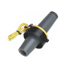
For a 15kV 200A loadbreak arrangement, the bushing well, bushing insert, and elbow belong to one coordinated interface. The YIEOU JY DTT-15/200 bushing insert, for example, is rated at 15kV and 200A and is designed to thread into a suitable bushing well for a corresponding loadbreak connection. Its official product data identifies a controlled current path and torque-controlled installation. Those details matter when the heat pattern is concentrated near the equipment interface.
Broad warming across the connector and cable
A broad temperature rise extending along the cable and Separable Connector is more consistent with load, cable sizing, enclosure temperature, or heat transferred from nearby equipment than with one small resistive point. Current still needs to be measured. The cable conductor, connector, bushing, and other accessories must all support the same continuous current path.
Airflow can also change the visible pattern. One phase beside a ventilation opening may appear cooler than an equivalent phase in a stagnant corner. A connector above a transformer tank or beside another heat source may be warmer because of its surroundings. The thermal image should be read together with the physical layout.
Table 1. Thermal Pattern and Investigation Direction
| Observed pattern | First information to compare | Possible connection issue |
|---|---|---|
| Small hot area near cable contact | Phase current, conductor size, contact range, installation record | Incorrect contact, poor crimp, damaged or contaminated conductor |
| Heat strongest near bushing interface | Engagement position, interface family, tightening record | Incomplete mating, incompatible parts, loose equipment-side connection |
| Whole connector and cable are warm | Current, cable loading, ambient temperature, ventilation | High load, undersized current path, enclosure heating |
| One phase differs from two similar phases | Individual phase currents and identical inspection conditions | Load imbalance or phase-specific contact problem |
| All phases changed from the historical baseline | System load, room temperature, equipment condition | Operating change or common cooling problem |
| Pattern changes after cable movement | Cable support, bending force, connector alignment | Mechanical strain affecting the interface |
The Current Path Must Be Matched as One Assembly
A Separable Connector rating is meaningful only when the surrounding components support the same duty. The cable conductor transfers current into a contact or lug. That contact transfers current through the Separable Connector and into the equipment bushing. A weak point anywhere in that sequence can dominate the temperature pattern.
Starting with the printed current rating alone can therefore lead to the wrong conclusion. A 600A Separable Connector body does not correct an unsuitable cable contact, and a compatible-looking bushing does not confirm the required mating dimensions. The complete assembly needs the correct voltage class, current class, interface, conductor connection, and installation method.
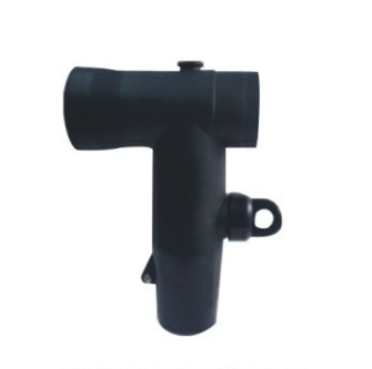
YIEOU’s American-style 600A product family includes deadbreak T-shaped connectors for higher-current equipment connections. Their role is to provide a secure screened connection within the matching 600A system. They are not loadbreak devices, and they should not be separated while carrying load current. When a 600A interface develops a thermal anomaly, the circuit must be handled under the applicable isolation, verification, and grounding procedure before any physical investigation.
European-style 630A Separable Connector products require their own review. The QJT 12/24-630A European-style front connector is specified for compatible Type C equipment bushings and for systems up to 24kV. Its published cable tables pair conductor cross-sectional areas with cable insulation diameters and adapter codes. This shows why “630A” alone does not define the assembly. Cable adapter fit and the equipment interface remain part of the current and insulation system.
The 600A and 630A values are close numerically, but the products may follow different interface systems and standards. A thermal investigation must never assume that parts, installation dimensions, or corrective actions can be transferred from one family to the other.
Load Current Changes the Meaning of Temperature
The same Separable Connector can show different surface temperatures as load changes. A useful survey records or measures the current at the time of inspection. Without that information, the image shows only the thermal condition at one moment.
Three comparisons are especially useful. First, compare the three phases when their construction and loads are similar. Second, compare the same connection at comparable load over time. Third, compare it with another connection of the same design in a similar enclosure. These comparisons help separate ordinary load-related warming from a developing local anomaly.
An apparently equal load still needs careful interpretation. Cable routing, Separable Connector position, nearby heat sources, and ventilation can create modest differences. A persistent concentrated hot area is more significant than a small diffuse difference that follows the enclosure layout. The trend matters as much as the snapshot.
It is also important to confirm whether the current is within the rating of the complete circuit. The Separable Connector, bushing, cable conductor, contact, junction, and equipment terminal must all be suitable. If several interfaces are connected through a junction or bus arrangement, each current path must be understood rather than assuming that the rating of one visible component defines the whole assembly.
A Connector is part of the electrical path, but it is also part of a thermal environment. Current produces heat; enclosure design and surrounding materials determine how quickly that heat leaves. Both sides of the problem must be reviewed.
Contact Selection and Installation Control Resistance
The conductor contact is a small Separable Connector component with a large influence on temperature rise. Its bore or mechanical range needs to match the actual conductor. Copper and aluminium conductors, compacted and conventional stranded conductors, and different cross-sectional areas can require different contact selections or preparation methods.
An unsuitable Separable Connector contact can appear mechanically secure while still producing an unreliable electrical interface. A contact that is too large may not develop the intended pressure. A contact that is too small may damage strands or prevent correct insertion. Oxide, dirt, moisture, or particles at the conductor surface can further affect the connection.
Installation tooling matters for the same reason. Compression contacts depend on the correct tool, die, and sequence. Mechanical or shear-bolt contacts depend on their specified procedure. Tightening a component “as much as possible” is not a valid substitute for the product instruction. Excessive force can damage parts, while insufficient force can leave an unstable connection.
The evidence available after installation also matters. Cable preparation dimensions, contact identification, tool and die records, installer checks, and commissioning results make a later thermal investigation more efficient. If those records are unavailable, the outage inspection may need to confirm more of the assembly.
For our Separable Connector matching work, conductor material, conductor construction, cross-sectional area, equipment interface, and cable dimensions are reviewed together. This reduces the chance that the connector body is correct while the internal current-transfer component is not.
Mechanical Strain Can Create an Electrical Symptom
The cable should arrive at the equipment interface without forcing the Separable Connector to hold its weight or correct its alignment. A heavy or stiff medium-voltage cable can apply continuous bending force if the support point is too far away, the trench is shallow, or the cable route is too tight.
That force can make installation difficult and may prevent the Separable Connector from reaching its intended position. It can also change the condition of the interface over time as the cable moves through load and ambient temperature cycles. A hot pattern that returns after corrective work may therefore require a review of cable support, not another attempt to tighten the connection.
Visible alignment offers a useful clue, but it does not confirm internal engagement. The equipment drawing, connector instruction, and relevant position indicators must be used. In a 200A loadbreak system, the elbow and bushing insert need to mate as designed. In higher-current deadbreak and European-style systems, the bolted or threaded connection arrangement needs the specified assembly procedure.
The cabinet must also provide room for installation and inspection. If the Separable Connector is crowded against a wall, another phase, or a rear accessory, the installer may not have enough space to prepare, align, and tighten the assembly correctly. Restricted airflow can then complicate the thermal pattern after energization.
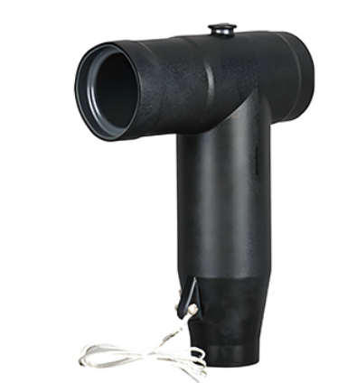
The QJT 12/24-630A front connector illustrates this interaction. Its Type C equipment interface, cable adapter, conductor connection, screened body, and grounding arrangement work as a coordinated system. A correct electrical specification still needs adequate cable bending space and mechanical support inside the RMU or switchgear compartment.
Infrared Inspection Needs a Repeatable Method
Thermal imaging is most valuable when Separable Connector inspections can be compared. The route, load range, viewing position, camera settings, environmental conditions, and component identification should be recorded consistently. This creates a baseline and makes a later change easier to recognize.
Equivalent phases provide a convenient reference only when their loads are also checked. A warmer phase may simply carry more current. Conversely, an abnormal high-resistance connection can sometimes carry less current and appear less warm than expected. Current measurement and the circuit arrangement remain essential.
Surface material also affects apparent temperature. Screened rubber surfaces generally behave differently from bare, polished metals, which can reflect surrounding infrared energy. Reflections from hot equipment, sunlight, or the inspector can create misleading spots. Comparing like surfaces from a consistent angle improves the quality of the observation.
The inspection report should identify the exact Separable Connector component and location. “Connector hot” is too broad. A better record states whether the apparent rise is near the cable contact, the equipment bushing, the center of the body, a rear connection, or the adjacent cable. It should also record phase current and reference temperatures from comparable components.
No infrared survey makes an energized connector safe to handle. Access boundaries, personal protective equipment, equipment ratings, and local operating procedures remain controlling. Any decision to inspect internally, retighten, disassemble, or replace a Separable Connector belongs in a planned de-energized work process performed by qualified personnel.
Corrective Action Starts With Cause Confirmation
Replacing the visible Separable Connector body without identifying the cause can allow the same problem to return. Corrective work should follow the evidence gathered from the thermal pattern, load data, records, and safe outage inspection.
If the heat is concentrated at the conductor contact, the investigation may need to confirm conductor condition, contact range, installation tooling, and compression quality. If the heat is strongest at the bushing, the interface family, engagement, equipment-side connection, and condition of both mating surfaces become more important. If the whole assembly is warm, current loading, cable size, compartment temperature, and ventilation deserve attention.
Damaged insulation, conductive surfaces, or contact components should not be casually reused. Medium-voltage cable accessories combine electrical, mechanical, sealing, and stress-control functions. A part that has been exposed to severe heat or incorrect assembly may require replacement according to the product requirements and engineering assessment.
Corrective work also needs a post-repair check. A later Separable Connector thermal inspection under comparable load can show whether the abnormal pattern has disappeared. Where the project procedure requires additional electrical tests, those results should be reviewed with the thermal trend rather than treated as unrelated records.
Table 2. Information for a Separable Connector Overheating Review
| Information | Why it matters | Useful evidence |
|---|---|---|
| Phase current and load profile | Separates load-related heat from local resistance | Current measurement and operating record |
| Connector family and rating | Defines interface and operating category | Model, label, datasheet, equipment drawing |
| Cable conductor | Determines contact selection | Material, construction, cross-section |
| Cable insulation diameter | Determines adapter and stress-control fit | Cable datasheet and measured diameter |
| Equipment bushing | Confirms mating compatibility | Bushing type, marking, dimensional drawing |
| Installation method | Shows whether contact and engagement were controlled | Tool, die, torque, bolt, and inspection records |
| Cable support and layout | Reveals sustained mechanical strain | Compartment drawing and site photographs |
| Thermal comparison | Establishes location and trend | Same-load phase comparison and prior images |
| Environment | Explains cooling and reflected heat | Ambient temperature, airflow, nearby heat sources |
Specify the Connection to Prevent Repeat Problems
Separable Connector thermal reliability begins before installation. A project specification should define the actual equipment interface, voltage class, continuous current, cable conductor, insulation diameter, contact type, connection arrangement, and installation environment. These details allow the full kit to be matched rather than assembling parts from similar-looking families.
For 200A loadbreak systems, the elbow, bushing insert, junction, cap, and related components must belong to the correct compatible interface. For 600A American-style deadbreak systems, the T-body, bushing, busbar, and rear accessories follow that system’s requirements. For 630A European-style systems, the Type C or other specified interface, cable adapter, contact, and front or rear arrangement must be confirmed independently.
This separation is important when an existing hot Separable Connector is being replaced. A maintenance team may identify the cable size and current rating but still lack the bushing designation or insulation diameter. Ordering from those two numbers alone can reproduce an interface or adapter mismatch.
When customers provide the equipment drawing, bushing marking, existing connector model, cable datasheet, load information, and compartment layout, we can match the Separable Connector and its cable-side components more accurately. Clear thermal photographs and inspection records can also help explain why the replacement is being considered, although they do not replace the dimensional and electrical data.
Conclusion
Separable Connector overheating is a system symptom. The temperature pattern must be interpreted with load current, connector family, conductor contact, equipment bushing, cable dimensions, installation method, mechanical support, and enclosure conditions. A concentrated hot spot points the investigation in a different direction from broad load-related warming, but neither pattern proves a cause on its own.
YIEOU manufactures each Separable Connector family for its corresponding medium-voltage interface system and can review the connection as a complete assembly. Keeping 200A loadbreak, 600A deadbreak, and 630A European-style arrangements distinct is essential when diagnosing a hot connection or preparing a replacement.
FAQ
Is any warm Separable Connector defective
No. Normal load, ambient temperature, nearby equipment, and restricted airflow can warm the Separable Connector surface. The useful check is whether the pattern differs from comparable phases under similar load or has changed from a reliable baseline.
Can a thermal camera identify a loose contact
It can reveal a pattern consistent with increased resistance, especially a localized hot area compared with similar loaded connections. It cannot prove that the contact is loose. Load measurements, records, and a safe de-energized inspection are needed to confirm the cause.
Why should phase current be measured during inspection
Heat rises as current increases, so a more heavily loaded phase may normally appear warmer. Without current data, load imbalance can be mistaken for a connector defect.
Can 600A and 630A connectors be evaluated as the same system
No. A 600A American-style deadbreak system and a 630A European-style system may use different equipment interfaces, standards, contact arrangements, and accessories. Their similar current values do not make the parts or procedures interchangeable.
Does cable cross-section determine the replacement kit
No. Conductor area helps select the contact, but insulation diameter, conductor material and construction, voltage class, equipment bushing, and connector family also affect the kit.
Should a hot deadbreak connector be disconnected immediately
A deadbreak connector must not be separated while carrying load current. The response should follow the site’s approved operating and safety procedure, including isolation, verification, and grounding before physical work.
What information helps YIEOU review an overheating problem
Useful information includes the connector and bushing models, system voltage, phase currents, cable datasheet, thermal images, installation records, compartment drawing, and operating environment. These details help us distinguish product matching questions from load, workmanship, or layout issues.