
At the base of a wind turbine, the medium voltage cable connection has to share a working space with equipment doors, cable supports, earthing conductors, and the route into the collector network. In a nearby transformer enclosure, the same connection may face a different arrangement, even though it serves the same turbine. This is where a compact cable interface becomes useful: it allows the cable to meet an enclosed equipment bushing without turning the compartment into an exposed termination area. A Separable Connector belongs in that practical discussion, alongside the actual cable route and the way the turbine connection will be maintained.
Quick Answer
A Separable Connector for a wind farm needs to suit the equipment bushing, the operating voltage, the circuit current, and the installed cable. Its value is the screened, detachable connection between the cable and compatible equipment. That value is most apparent where tower base switchgear or an adjacent prefabricated substation has limited space and requires access during planned outages.
At YIEOU, we manufacture medium voltage cable accessories, including European-style front and rear connectors for matching 35kV equipment. We offer these as connection components with defined application limits. We do not treat a wind turbine power rating as a shortcut to a particular connector, and a detachable connection does not take over the switching function of the switchgear. The useful choice is the complete connection that fits the location and remains accessible after installation.
The Turbine Connection Has Its Own Working Environment
Wind farm connections are repeated across a site, but the location of the equipment changes what the cable interface experiences. Switchgear may sit inside the tower base, while the transformer may be installed in a separate enclosure beside it. A connection that is convenient in an open factory assembly area can become awkward once the equipment is positioned, the cable enters through the floor, and the door has only a limited opening. We approach our connector application around that installed setting, rather than assuming every turbine uses the same arrangement.
For a switchgear builder, a screened connection provides a defined way to bring the cable onto the equipment bushing. For the contractor installing a prefabricated substation, it provides a compact interface inside the cable compartment. The benefit is practical: the cable connection can remain enclosed while retaining a separable interface for suitable maintenance work. A Separable Connector does not remove the need for an enclosure, cable support, or an electrical isolation procedure. It makes the cable-to-equipment boundary easier to organize when those surrounding provisions are in place.
The tower base also differs from a continuously occupied electrical room. Access may be occasional, and the equipment can remain closed for long periods between visits. We therefore consider the condition of the completed interface together with the ease of seeing and reaching it. A Separable Connector hidden behind other cables might fit at assembly, yet leave little room for later inspection. The most useful arrangement keeps the body, its grounding connection, and the cable support visible from the normal service position.
Our Separable Connector range serves this cable interface role. It is relevant to turbine-associated medium voltage equipment when the connection system matches; it is not a connector for generator control wiring or low voltage auxiliary circuits. Keeping that role clear avoids selecting an accessory merely because it carries the broad label of a wind power component.
Compact Compartments Need Room Beyond the Connector Body
The attraction of a Separable Connector in a turbine connection is often its compact shape. However, the body occupies only part of the space needed for a usable cable entry. The cable has to rise from its entry point, bend toward the bushing, and reach the connection without pulling it sideways. The grounding lead needs a clear route as well. We regard that complete installed shape as the relevant footprint, especially in a tower base where the surrounding steelwork and access position are already fixed.
A downward cable entry can look straightforward on a cabinet drawing. In practice, the cable may arrive at an angle because of the trench, duct, or floor opening outside the compartment. If the first support is too far away, the connection may be used unintentionally to hold the cable in position. A compact Separable Connector cannot correct that layout. Our screened connector bodies form the electrical interface; independent support carries the cable weight and keeps persistent bending force away from the connection.
Where a wind farm uses a compatible 35kV European-style connection, our front connector fits naturally into this arrangement. It brings the cable to the equipment interface while keeping the connection enclosed within its screened structure. The surrounding space still needs to accommodate the actual cable bend and the approach for installation. This is why we consider a Separable Connector in its installed position, with the door, phase arrangement, supports, and grounding route included.
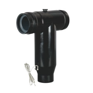
Another useful distinction is between fitting the body and being able to work on it. A cable compartment can have enough space for the finished Separable Connector assembly but too little clearance for access to the rear closure or connection hardware. That difference becomes important during an outage. A layout that leaves the relevant surfaces reachable reduces the need to move adjacent cables simply to expose one connection. It also preserves the intended route when a cable is reconnected.
We keep these practical considerations close to the application. There is no benefit in making the compartment larger than necessary, but reducing its depth until the cable presses against the door defeats the compact connection. The right balance is a short, natural cable route and enough room for the completed assembly to sit without pressure from neighboring components.
Voltage and Interface Boundaries Stay Clear Across the Site
A wind farm may contain equipment from different manufacturers and may use more than one connection arrangement. The turbine transformer and the collector switchgear do not automatically share the same cable interface. We manufacture accessories for defined systems, so the equipment bushing remains the starting point for compatibility. The Separable Connector at each location has to belong to the connection family used there, even where the cables have similar conductor sizes.
Our 35kV European-style front and rear connectors are rated at 630A for their stated applications. That gives a concrete product direction for matching equipment, without making every 630A accessory interchangeable. The bushing geometry, contact arrangement, insulation fit, and voltage class still have to agree. A 600A American deadbreak connection and a 630A European-style connection are distinct systems. Similar current numbers do not make their parts substitutes for one another.
The same limit applies to voltage. A Separable Connector used at one medium voltage level cannot be moved to a higher-voltage connection simply because the external shape looks similar. A Separable Connector that suits one turbine installation may be unsuitable for another site with a different collector voltage. We keep the rating of the selected accessory tied to the actual connection, rather than describing our entire range as suitable for any wind farm.
Circuit current is another local requirement. Turbine output gives useful application context, but it does not independently specify the accessory. The electrical duty at the connection, including the relevant continuous and fault requirements, remains part of equipment coordination. The cable accessory is one component in the circuit, and its nameplate current is not a complete statement about the capacity of the wind farm.
For an equipment builder, this means the connection can be consistent within a chosen platform while remaining different from the arrangement used elsewhere on the site. We offer compatible product families for that purpose. We do not imply that a common appearance provides cross-system compatibility or that replacing the connector alone changes the equipment rating.
The Installed Cable Determines the Final Fit
The cable entering a turbine connection may be selected to suit the route between equipment and the collector network. Its conductor size is important, but the accessory also meets the outside of the insulation and the prepared conductor connection. Two cables with the same nominal cross-section can differ in those details. We therefore treat the cable side of a Separable Connector as a fitted assembly, rather than as a socket defined only by a square-millimeter value.
The diameter over insulation governs the fit of the cable adapter around the cable. That fit helps the intended assembly maintain its insulation and sealing arrangement. The conductor material and construction govern the contact configuration. These are separate requirements, which is why a larger conductor number is not the whole answer when changing cable. We offer our front and rear connectors in cable configurations within the stated product range; the particular version still has to suit the cable installed at that connection.
This becomes especially relevant when a wind farm uses different cable constructions at separate equipment locations. The cable in a tower base may not be the same as the cable supplied for an external transformer enclosure. A Separable Connector that fits one is not proven suitable for the other by matching the conductor cross-section alone. A Separable Connector can have the correct equipment side and still need a different cable adapter or contact on the cable side.
Installation quality also affects whether the intended fit is achieved. Clean insulation surfaces, correctly prepared cable ends, the specified contact connection, and proper seating belong together. We supply the accessory as a defined product assembly; its components are not an invitation to compensate for inaccurate preparation by forcing the rubber body into position. The useful outcome is an interface that follows the product instructions and sits naturally on the cable and equipment.
Our cable configurations suit the actual cable, and qualified installation follows the accessory instructions. When a cable changes, the fitted components deserve fresh confirmation even if the switchgear has stayed in place. That is a more useful connection decision than assuming the previous body can accept any replacement cable of the same nominal size.
Additional Cable Paths Need a Compatible Assembly
Some wind farm equipment locations need a second cable connection, while others need only a single equipment entry. That difference affects the assembled depth and the position of the cables in the compartment. We offer front and rear connection arrangements for compatible systems, allowing the Separable Connector configuration to follow the actual cable paths. A rear Separable Connector is useful where the selected front connection supports it and the equipment arrangement calls for that additional path.
In a matching 35kV European-style assembly, our rear connector can be used with the corresponding front connector. This gives an enclosed arrangement for the additional cable connection without introducing a separate exposed connection point. The practical benefit is most apparent where a prefabricated substation has a constrained compartment. The benefit remains conditional on a compatible assembly and sufficient working space; a rear component does not create room where the enclosure is already too shallow.
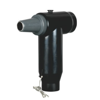
The distinction matters on a wind farm because additional cables can be confused with additional capacity. Fitting another Separable Connector does not by itself increase the rating of the equipment bushing, the front assembly, or the associated circuit. Its role is to provide the specified connection arrangement. We keep the full assembly within its electrical limits rather than interpreting the number of attached cables as a new rating.
A second path can also change the service experience. The cable on the rear Separable Connector may occupy the space previously used to access a closure or grounding point. Its support may have to sit in a different location from the first cable support. We consider these consequences as part of the installed configuration, so the additional path does not make the original connection inaccessible. The assembly needs to work for both cables in the actual compartment.
For equipment intended for later expansion, space reserved around the connection has value even before the second cable is fitted. That is a physical provision, not a promise that any future accessory will fit. Our compatible front and rear components provide a defined product direction, while the final arrangement stays tied to the chosen voltage class, interface system, and enclosure.
Wind Farm Exposure Makes the Whole Enclosure Relevant
A wind farm cable interface can be sheltered inside equipment and still experience moisture, dust, or seasonal changes in temperature. Tower doors open during maintenance, cable entries can admit damp air, and an outdoor substation enclosure faces its own weather exposure. We manufacture screened and sealed cable accessories for their specified operating conditions. We also keep the distinction between the accessory seal and the surrounding equipment environment clear.
The Separable Connector provides protection at its intended interfaces when assembled correctly. It does not waterproof every cable entry, remove condensation from the compartment, or protect unrelated equipment from water ingress. Our 35kV front and rear products use molded EPDM bodies with shielding and sealing features. Those features support the enclosed cable connection, while enclosure drainage, entry sealing, and environmental control remain relevant to the completed installation.
Coastal wind farms require particular care with that boundary. Salt contamination and persistent moisture may affect exposed metalwork, grounding connections, and equipment surfaces around the accessory. We do not extend ordinary indoor or outdoor suitability into a blanket offshore approval. Severe salt spray, unusual exposure, and high vibration are special conditions that require the appropriate product and equipment suitability. A Separable Connector suitable for a sheltered compartment is not automatically qualified for every marine environment.
Grounding remains part of the completed screened connection. The grounding lead needs a secure attachment and a route that will not be trapped by a door or strained by adjacent cables. Within the assembly, the Connector performs the cable interface role; the surrounding grounding arrangement supports the intended screened installation. This is a practical reason to leave the grounding point visible instead of hiding it behind the body.
We keep environmental claims specific because wind farm conditions vary widely. An inland site, a coastal enclosure, and a high-altitude installation do not present identical demands. Our Separable Connector range includes defined operating conditions and special-condition options, but the application stays within the suitability of the selected assembly. Separable Connector suitability depends on the actual compartment environment, not simply the word outdoor on a project description.
Planned Outages Need Accessible Connections and Protected Spare Ports
Wind farm maintenance involves more than opening an equipment door. The cable connection has to be reached, isolated through the appropriate equipment, and handled under the applicable electrical procedures. A Separable Connector offers a detachable interface for suitable work after the required isolation and safety checks. Deadbreak arrangements do not interrupt load current, and their detachable structure is not permission to separate an energized connection.
We consider maintenance access while the original layout is still being established. The connection body, closures, grounding leads, and cable supports need to remain reachable without forcing nearby cables aside. This is particularly valuable in a tower base, where the working position may be constrained by the surrounding structure. A Separable Connector that can be inspected from its intended service position is easier to assess than one concealed by an added cable path.
Spare equipment interfaces also need appropriate protection. A shipping cover keeps an item clean during transport; it is not automatically a rated insulating component for an installed spare connection. We offer European-style insulating caps for corresponding 24kV and 35kV equipment interfaces. In a compatible wind farm installation, the cap closes the unused interface while retaining the intended insulation and screened protection. The voltage class and interface fit remain relevant even though no cable is attached.
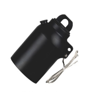
That distinction supports staged installation as well as later changes. An unused interface can remain properly protected while the operating cable connection stays in service. The cap is selected for the actual spare port, rather than borrowed from an unrelated system because it appears to fit. The Separable Connector and the spare-port protection serve different positions in the arrangement, and each needs its own correct application.
Our Separable Connector configurations help keep turbine-associated cable connections compact, screened, and accessible within compatible equipment. An effective arrangement is one that preserves a natural cable route, stays within its product limits, and allows the intended maintenance work without disturbing adjacent connections. That is the role we support as the manufacturer of the cable accessories.
Frequently Asked Questions
Where does a Separable Connector fit in a wind farm?
It connects a medium voltage cable to a compatible equipment interface, such as turbine-associated switchgear or an adjacent prefabricated substation. Its location depends on the equipment arrangement. It is not used as the connector for low voltage control or auxiliary wiring.
Can a deadbreak connection switch off the turbine circuit?
No. A deadbreak Separable Connector provides a cable connection and does not perform load switching. Isolation and the required safety checks belong to the appropriate equipment and operating procedures before the connection is handled.
Does every wind farm use the same voltage class?
No. The actual equipment connection determines the required accessory voltage class. Our 35kV connector examples apply to matching 35kV arrangements and do not establish suitability for a higher-voltage collector system.
Why does cable insulation diameter matter?
The adapter fits around the cable insulation, while the contact fits the conductor. Nominal conductor cross-section alone does not describe both interfaces. A Separable Connector therefore needs the correct cable configuration even when its equipment side already matches.
Is a rear connector suitable for every second cable?
No. We offer rear connections for compatible front assemblies within the stated system limits. The additional cable also changes the space and support requirements, so the assembled arrangement has to fit the compartment.
Does a screened connector remove moisture concerns?
No. The accessory seal protects its intended interfaces under the specified conditions. The surrounding enclosure, cable entries, condensation, and any severe coastal exposure still affect the installation environment.
What protects an unused medium voltage interface?
A matching rated insulating cap provides the intended protection for a spare equipment interface. A transport cover is not an automatic substitute. We offer corresponding European-style caps for compatible installations, with the voltage class, interface, and grounding arrangement kept consistent.