
An underground utility tunnel can make a city cable route easier to reach, but reaching a cable is different from reaching a usable connection. At a branch cabinet or equipment chamber, the available working area may already be shared with cable supports, ventilation equipment and other services. A Separable Connector that fits the electrical rating can still create an awkward installation if its cable approach or removal space has been overlooked. For electrical contractors, switchgear and equipment manufacturers, the useful question is where a detachable connection supports the urban distribution route, and how that connection will remain accessible once the tunnel is in service.
Quick Answer
A Separable Connector is useful at compatible medium voltage equipment and branching points within an urban utility tunnel. It provides a defined cable interface that can be separated during a properly isolated maintenance operation. Its value comes from matching the equipment bushing, cable construction and connection layout while keeping the joint protected and accessible.
We manufacture separable cable accessories for different equipment systems, including American-style deadbreak connections and European-style screened arrangements. A tunnel location does not make those systems interchangeable. The practical starting point is the equipment interface, followed by the electrical duty, cable fit and conditions at the actual service position.
Put the Connection Where the Cable Route Meets Equipment
Most of the length of a tunnel feeder is simply a cable route. The meaningful connection points occur where that feeder reaches switchgear, a transformer or a distribution branch cabinet. A Separable Connector at one of these positions creates a service boundary between a cable and the equipment it supplies. It does not need to appear at every change in cable direction or every support bracket along the route.
This distinction matters during urban upgrades. A long feeder may remain in place while a branch cabinet is replaced or an additional distribution point is introduced. A Separable Connector can make the equipment connection a defined assembly, provided the replacement equipment uses a compatible interface. The cable itself still has to be in suitable condition and able to reach the new termination position without being pulled or sharply bent.
At YIEOU, we manufacture American-style Separable Connector products alongside bushings, branching accessories and insulating caps. In a tunnel equipment chamber, those components serve different parts of the connection. The cable accessory forms the cable termination, the equipment bushing establishes the mating interface, and a suitable protective accessory closes any interface that remains unused.
A useful layout therefore begins with the service point rather than the longest cable run. The cabinet position determines how a worker can approach the connection, where the incoming cable can be restrained and whether another component blocks access. This keeps the detachable interface connected to a practical maintenance purpose throughout the installation.
Underground Conditions Make the Complete Seal Important
A utility tunnel protects equipment from direct exposure to road traffic and open weather, yet the connection may still face moisture, dust or water entering through building interfaces. Conditions near an entrance shaft can differ from those in a ventilated equipment room. For a Separable Connector, a description such as underground installation is too broad to define the environment around every termination.
Our American-style front connection range includes molded EPDM bodies intended to provide an insulated, sealed interface in corresponding equipment. That construction is useful where a cable enters a branch cabinet along an underground route. The assembled seal depends on the matching components and their condition, including the cable-side fit and the mating equipment surface. The Separable Connector body alone cannot compensate for a damaged interface or an incorrectly fitted adapter.
It is also important to separate an accessory’s environmental capability from the performance of the whole installation. A sealed Separable Connector does not establish a flood rating for its cabinet, protect unrelated terminals or remove the need for drainage. If a chamber can flood, the required exposure conditions apply to the assembled equipment and every relevant entry point. General moisture resistance is not a substitute for that assessment.
Keeping the connection surface clean has a practical effect on installation quality. Dust left on a mating surface can be trapped during assembly, even in a finished tunnel that appears cleaner than an open construction site. Protected storage and a clean assembly position help preserve the intended interface. We provide the connection components as a matched product arrangement; the installation environment has to allow that arrangement to be assembled correctly.
Match the Bushing Before Choosing the Connector Shape
A tunnel project may contain equipment supplied at different times or built around different connection systems. Similar voltage descriptions do not establish a common interface. A T-shaped Separable Connector can belong to an American 600A system or a European 630A arrangement, with different mating requirements. Selecting a Separable Connector by its outline can therefore create a mismatch before the cable is even prepared.
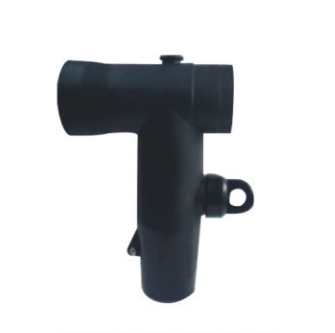
For an American-style equipment bushing, our JY QJT-600 front connector is offered in 15kV and 24kV versions with a 600A interface. It is a non-load-breaking accessory for the corresponding equipment connection. In a tunnel branch cabinet built around that system, the front connector provides the equipment-side connection while the rest of the assembly follows the same compatible family. The current figure does not authorize connection to a European bushing carrying a nearby numerical rating.
The cable side of the Separable Connector deserves the same attention. Conductor cross-section describes the amount of conductor material, while the diameter over insulation determines part of the fit between the cable and its insulating accessory. Two cables with the same cross-section can have different insulation dimensions. Conductor material and construction also affect the contact arrangement. A Separable Connector therefore needs both an equipment-side match and a cable-side match.
For existing urban feeders, the cable marking and its physical condition can be especially relevant because the cable may predate the replacement cabinet. Assuming that an old termination identifies every detail of the replacement kit can carry an earlier mismatch forward. We offer distinct connection systems so that the actual cable and bushing can be matched without treating the connector body as a universal adapter.
Branching Points Need Space for Every Connected Cable
Branching is one reason to introduce a service point into an urban tunnel route. A feeder may continue along the corridor while a separate cable serves a nearby distribution room. The connection then has to accommodate more than one cable direction, and the space occupied by the completed assembly becomes more important than the footprint of an empty cabinet.
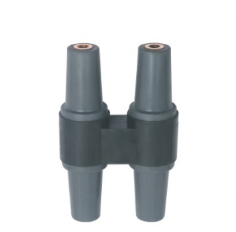
Our JY HDJT-12/24kV 630A deadbreak H junction is intended for underground and outdoor cable distribution applications and corresponding European-style branch equipment. It connects with matching 630A screened front connectors. This provides a different branching arrangement from the American front connection described earlier. The two examples show alternative equipment systems; their parts do not form one mixed assembly.
At a junction, a Separable Connector on one branch can be physically close to the adjacent cable. Each cable still needs a supported approach to its own interface. If several cables are forced into the same narrow bend, removing one connection may require disturbing another. A compact assembly is useful only when the surrounding cable routes leave the intended service positions reachable.
Table 1. Connection Positions Along an Urban Utility Tunnel
| Service position | Useful connection role | Layout condition that matters |
|---|---|---|
| Equipment chamber | Terminate the feeder at a compatible bushing | Leave access to the complete cable connection |
| Branch cabinet | Connect the main route and a defined branch | Support each cable without loading the mating interface |
| Reserved distribution point | Keep an unused interface protected | Fit the correct service-rated protective accessory |
| Tunnel-to-building transition | Connect the route to local distribution equipment | Allow the cable approach and equipment access to coexist |
A branch connection also has an electrical role that remains separate from its geometry. Adding an outlet does not increase the permissible loading of the upstream path, and a junction does not provide circuit protection. The Separable Connector assembly fits into the circuit arrangement established by the distribution equipment. Its contribution is the insulated connection at the selected service point.
Spare Interfaces Need Protection From the First Stage
Urban infrastructure is often built in stages. A tunnel branch cabinet may be installed before every connected building or feeder is ready. An unused Separable Connector interface is still part of the electrical assembly, even when the future cable has not arrived. Leaving that position with temporary transport protection can undermine the quality of the completed service point.
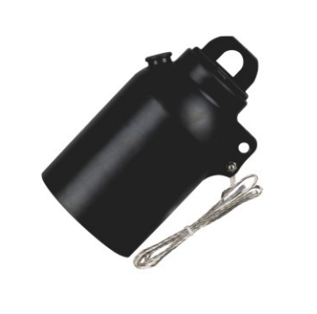
We offer the JY JYM-600 insulated protective cap for corresponding 15kV and 24kV 600A interfaces. In an American-style connection arrangement, this accessory provides the appropriate insulated closure for a compatible spare position. It is a different function from covering an opening to keep packaging dust away. The protective accessory has to match the actual interface and its intended condition in service.
A Separable Connector installation with a planned spare point also needs enough room for the future cable. A cap can preserve the unused interface, but it cannot create cable bending space after other services have filled the chamber. Reserving a usable cable route alongside the protected position makes the later connection physically possible without rearranging the original terminations.
The closure and its grounding provisions remain relevant while the point is unused. A Connector interface is part of an electrical assembly, and an unused position can still require service-rated insulation and protection. Its appearance as a spare does not mean it is harmless or available for unplanned access. Any later change follows the operating and isolation requirements of that equipment system.
A Detachable Connection Still Needs Working Room
A cable compartment can look spacious before its cables are installed. Once several feeders enter from a tunnel tray, the remaining room may be much smaller. The Separable Connector body occupies only part of the space needed for installation and maintenance. The cable bend, support arrangement, tools and direction of removal all affect whether the service point can actually be used.
At a Separable Connector, the most useful support position prevents cable weight and stiffness from being carried by the connector interface. A heavy feeder can otherwise pull against the body or push it out of alignment. This becomes particularly noticeable where the tunnel cable tray is offset from the cabinet entry. Moving the connection into line with a strained cable does not solve the mechanical problem; the cable approach has to suit the equipment connection position.
Access also changes after the tunnel becomes operational. A pipe support, ventilation duct or later cable tray may occupy space that was open during initial installation. At a service chamber, the working position around the Separable Connector needs to remain part of the final arrangement. Preserving that access is more useful than relying on the fact that an installer could reach the interface before adjacent services were completed.
For equipment builders, this affects the choice between a compact connection body and a complete arrangement that is practical to service. We offer different cable accessory structures for defined equipment interfaces, but no connector shape removes the need for a workable cable route. The selected assembly and the enclosure layout have to be considered together, particularly where several connections share the same side of a cabinet.
Plan Maintenance Around the Equipment Operating Duty
Detachable connections can support equipment replacement and planned inspection, but detachable does not describe permission to separate a live circuit. A deadbreak Separable Connector is disconnected only under the appropriate de-energized and isolated conditions. The switches and protection devices determine how the circuit is taken out of service. The cable accessory provides the connection after those operating conditions have been established.
This distinction is important in a shared tunnel because the nearby cable routes may remain in service while work is planned at a particular cabinet. Physical access to a Separable Connector is not proof that the relevant circuit has been isolated. The equipment’s operating procedure, identification and verification govern the work. A test point or indicator has its own defined purpose and cannot be treated as a universal substitute for the required verification method.
A 200A loadbreak system has a different operating duty within its specified matching arrangement. It is not a direct replacement for an American 600A deadbreak connection or a European 630A system simply because a loadbreak function would be convenient. Choosing the Separable Connector family remains an interface and duty decision. Any change in operating requirements belongs with the equipment arrangement as a whole.
Our manufacturing includes dimensional and electrical verification capabilities for the accessories we supply. Those checks support the product interface and insulation requirements, while site acceptance addresses the installed assembly under the applicable procedure. For a tunnel service point, both matter: the accessory needs the correct construction, and the finished installation needs an accessible, properly assembled connection.
Keep Each Service Point Useful as the Tunnel Develops
The strongest reason to use an American-style Separable Connector at a matching tunnel service point is the defined connection it creates between the cable and equipment. That benefit lasts when the cable fit, interface family, environmental conditions and working area remain consistent with the original arrangement. A later cabinet change or added feeder can alter more than the number of occupied outlets.
We manufacture the cable connection bodies and associated accessories for these different arrangements, from American front connections and protective caps to matching European branching components. At YIEOU, the useful product configuration is the one that fits the service point as it will be installed and maintained. Keeping that connection accessible gives the tunnel’s maintainable cable route a practical equipment interface.
FAQ
Does every cable run in a utility tunnel need a Separable Connector?
No. These accessories belong at compatible equipment or branching interfaces where a detachable connection has a defined purpose. Continuous cable routes and cable-to-cable joints have different requirements, so a tunnel does not call for a connector at every support or change of direction.
Can a sealed connector be installed in a chamber that may flood?
Possible water exposure has to be assessed against the specified capability of the complete assembly and enclosure. General moisture resistance does not establish suitability for a particular water depth, exposure duration or contaminated floodwater condition.
Can one Separable Connector fit both 600A and 630A equipment?
Not on the basis of current rating alone. American 600A and European 630A systems have different interface requirements. The equipment bushing and the complete mating arrangement determine compatibility.
Why is cable cross-section insufficient for matching?
The accessory also has to fit the diameter over insulation and the conductor contact requirements. Cables with an identical nominal cross-section can differ in insulation size, conductor material or construction, so the full cable specification affects the connection.
What protects a spare connection before the next feeder is installed?
Use the service-rated protective accessory intended for that exact interface and operating condition. For corresponding American 15kV or 24kV 600A positions, our JY JYM-600 protective cap provides an insulated closure. Temporary transport covers do not automatically serve the same function.
Can a deadbreak connector be opened to isolate a tunnel branch?
A deadbreak accessory does not perform load switching. The circuit must be taken out of service and isolated through the appropriate equipment and procedure before the connection is separated. A Separable Connector body is not a substitute for a switching device.