
In a residential development, the medium-voltage cable route may disappear beneath roads and landscaped areas, but its connection points still need a clear purpose. A cable tap box can distribute an incoming supply toward several transformer locations, while each transformer serves the low-voltage network beyond it. These connections must remain accessible after pavements, fences and planting are complete. For equipment manufacturers and project contractors, the number of homes alone does not establish which cable accessory belongs at each position. The equipment interface, feeder duty and cable construction determine whether the connection can be assembled correctly and maintained later.
Quick Answer
A Separable Connector provides a detachable, insulated connection at the medium-voltage equipment serving a residential underground network. Its practical value is concentrated at accessible cable tap boxes and transformer interfaces, where a defined connection can support installation, inspection and planned equipment work without treating the entire buried route as one permanent assembly.
At YIEOU, we manufacture American-style cable accessories and cable tap boxes for these distribution applications. Our DFW-12kV arrangement distinguishes a bolted 600A main circuit from a 200A plug-in branch circuit. That distinction matters: a loadbreak branch accessory and a deadbreak main connection have different operating duties. A suitable Separable Connector arrangement matches the equipment bushing, voltage class, conductor contact and cable insulation fit before its convenience becomes useful.
Where the Underground Cable Becomes an Accessible Connection
Residential underground distribution combines long cable runs with a smaller number of serviceable equipment positions. The cable between two enclosures may pass beneath a road, but its termination belongs inside equipment intended to provide controlled access. This is where a Separable Connector can make the equipment connection detachable while maintaining the required insulation and shielding arrangement.
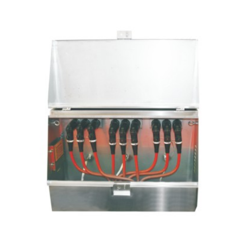
Our DFW-12kV American cable tap box is intended for cable distribution networks, including residential areas and densely populated urban locations. Its one-sided door access and transverse multi-pass busbar arrangement bring several cable connections into a defined enclosure. The enclosure provides the physical setting; the accessories establish the individual cable interfaces. A compact box therefore needs to be understood together with the connections and cable routes it contains.
A cable tap box also has a different purpose from the devices that control and protect its circuits. The Separable Connector establishes the cable interface; it does not automatically provide overcurrent protection or replace an equipment switch. This distinction helps keep the residential arrangement understandable when several branches share the same enclosure. An outgoing cable position can be convenient to access while still depending on protection and switching elsewhere in the network. The connection layout and the circuit control arrangement therefore need to be understood together, especially where later housing phases introduce additional equipment or another possible supply path.
This application is different from connecting household appliances or supplying an apartment distribution board. The medium-voltage accessories are upstream of the transformers that supply those low-voltage circuits. Their ratings and interfaces follow the medium-voltage equipment, even when the final demand comes from ordinary residential loads.
An accessible Separable Connector also gives a buried cable a practical endpoint during equipment replacement. Whether that cable can actually be reused depends on its condition, available length and suitability for a new termination. Detachability does not make a damaged cable sound or restore length lost during earlier preparation. It creates an equipment interface that can be addressed during planned work.
Main Feeders and Transformer Branches Need Different Connections
A residential cable tap box may contain connections with different functions. The incoming or through feeder carries the duty assigned to that part of the network, while an outgoing branch serves its own downstream equipment. Calling every visible termination a plug-in connection hides an important distinction between the main current path and the branch interfaces.
In our DFW arrangement, the 600A main circuit uses a fixed, screw-bolted connection, and the 200A branch circuit uses a plug-in connection. These values identify the relevant connection arrangements. They do not establish the allowable loading of every installed cable, the transformer capacity or the protection settings. The usable Separable Connector duty still depends on the completed circuit and its equipment limits.
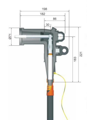
For a compatible branch, our JY ZT-15/200 loadbreak elbow provides a 15kV-class, 200A cable termination. The right-angle shape directs the cable away from its mating interface and can suit the cable approach inside a compact enclosure. We use molded EPDM insulation and a semiconductive shielding structure to form the cable accessory around its conductive connection. Those features support the termination; they do not replace the enclosure or the cable support.
A Separable Connector with loadbreak capability can perform its specified operation only within its rated conditions, with the correct mating components and operating procedure. The bolted main connection does not acquire that capability because a loadbreak branch is installed nearby. Deadbreak connections require the appropriate de-energized condition for separation.
Table 1. Connection Roles in a Residential Distribution Enclosure
| Connection position | Relevant arrangement | Practical implication |
|---|---|---|
| Main feeder connection | Specified bolted 600A main circuit in the DFW arrangement | Keep main-circuit duty and deadbreak operation distinct from branch operation. |
| Transformer branch | Matched 200A loadbreak elbow and equipment interface | Match the branch cable and mating components within the applicable ratings. |
| Equipment bushing position | Compatible bushing connection or specified insert | Confirm both the equipment-side fit and the accessory-side interface. |
| Reserved connection position | Correctly rated insulating accessory for that interface | Protect the unused position and retain access for planned development. |
Cable Fit Starts Below the Conductor Size Label
A residential feeder drawing may identify a cable by conductor area, but that number describes only part of the termination. The conductive contact must suit the conductor, while the molded insulation and cable adapter must fit the cable’s insulation dimensions and construction. A Separable Connector can have the correct current rating and still be unsuitable for the actual cable entering the box.
The difference becomes clear when two cables have the same nominal conductor area but different insulation thicknesses or conductor construction. Their dimensions at the prepared insulation surface can differ. The termination must develop the intended interface pressure and stress-control geometry on that surface. The conductor lug and the insulating fit solve related but separate parts of the connection.
We offer the JY ZT-15/200 family for copper- or aluminum-core XLPE cables within its stated configuration range. The applicable conductor contact follows the cable material and construction. A suitable contact for one conductor does not establish the correct adapter for every cable with that same area. The actual diameter over insulation remains a necessary Separable Connector matching dimension.
For a residential Separable Connector, this is especially relevant when a retained feeder meets newly installed equipment. Older cable and new cable may have different constructions despite similar labels. Preparation space also changes if the new bushing is higher, lower or farther from the cable entry. A termination that fits electrically still needs enough sound cable to reach its final position without strain.
This is why we treat the cable connection as a complete assembly. Conductor contact, insulation fit, screen continuity and outer sealing must work together. Substituting one accessory solely because its conductor range appears suitable can leave another part of that assembly mismatched. Accurate cable fit is more useful than choosing the largest current rating available.
The Equipment Bushing Completes the Interface
The elbow is only one side of a detachable connection. On the equipment side, the bushing or bushing assembly establishes the mating surface, contact position and insulation geometry. A Separable Connector must belong to the same specified connection system as that equipment interface. Similar appearance does not establish that the contact and insulation will engage correctly.
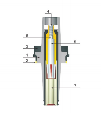
Where the equipment uses the corresponding insert arrangement, our JY DTT-15/200 single-pass bushing insert forms part of the 15kV-class, 200A interface. Its role is to provide the defined connection between the compatible equipment bushing arrangement and the cable accessory. It is not a universal adapter that makes every enclosure or transformer accept the same elbow.
The product reference to IEEE 386 is relevant to this American-style connection system. European-style 630A interfaces belong to a different matching decision. A residential installation does not become compatible with a 630A T-body simply because the equipment has spare space or because a higher current rating seems attractive. The mating interface must be established first.
There is also a difference between adding a second connection position and increasing circuit capacity. A multi-pass busbar or branching accessory can offer more connection locations while retaining limits on the shared conductive path. The number of outlets does not multiply the rating of the incoming circuit. In a residential Separable Connector arrangement, each branch and shared connection retains its own duty.
The physical term Connector can cover many connection designs, but the medium-voltage mating details determine the actual fit. Keeping those details consistent across the equipment bushing, insert and elbow avoids an assembly that looks complete while its contact or insulation engagement remains incorrect.
A Compact Enclosure Still Needs Cable and Working Space
Residential sites often favor small enclosures because the equipment must share space with paths, boundary walls and landscaping. Our DFW cable tap box uses a narrow arrangement and flexible combinations for these distribution positions. That helps accommodate the equipment footprint, but the Separable Connector still needs usable room inside and in front of the enclosure.
The cable route into a Separable Connector is one part of this space. A cable approaching from below needs enough room to turn toward the interface without forcing the elbow out of alignment. Its support should carry the cable weight and bending force rather than leave them acting continuously on the connection. A layout that fits when the door is open can still be unsuitable if the closed door presses against a cable or accessory.
Working access is a separate requirement. The installed arrangement needs room for the specified tools and permitted operating movement. Nearby fences, raised planters or parked vehicles can make an otherwise serviceable box difficult to approach. The available working area should remain useful after the development reaches its finished condition.
Outdoor exposure also affects the whole assembly. We offer fully insulated and sealed cable accessories, but an accessory’s protection rating does not describe every opening or component in the enclosure. Cable entries, doors, drainage arrangements and the equipment installation all influence moisture exposure. A Separable Connector cannot compensate for a box positioned where water repeatedly accumulates around its entries.
Construction conditions deserve attention before the equipment enters service. Dust, grit and moisture on mating surfaces can interfere with the intended insulation contact. Keeping interfaces protected until assembly and maintaining the specified cleanliness are practical parts of obtaining the connection’s intended performance. They matter particularly when the electrical enclosure is installed while nearby civil work continues.
Planned Maintenance and Later Housing Phases
A residential development may be completed in phases, with additional transformers or branches entering service later. A Separable Connector can provide a defined connection point for that future work when the equipment arrangement has been prepared for it. Reserved space is useful only when the interface, circuit duty and cable route remain suitable for the eventual connection.
An unused Separable Connector position needs the insulating accessory specified for that interface and service condition. A temporary transport cover is not automatically an in-service insulating cap. The difference matters when part of the enclosure is energized while another branch remains reserved. The completed arrangement needs to maintain its required insulation and screening at every active or unused position.
Later additions also need physical access to the original connections. A new branch cable should not block a previously accessible Separable Connector or make its cable support ineffective. Keeping the connection positions understandable helps installation teams identify what each accessory serves, but identification does not replace the electrical checks required before work.
Maintenance convenience has a specific boundary. A loadbreak Separable Connector supports only its defined operating duty; it does not authorize unrestricted disconnection, fault interruption or handling of exposed energized interfaces. A bolted deadbreak connection requires the proper isolation and de-energized condition. Work remains subject to the equipment procedure and the network’s possible supply paths.
The Separable Connector also remains part of planned equipment inspection. Displaced cable supports, visible damage, discharge marks or abnormal heating can indicate that further assessment is needed. The appropriate response depends on the equipment and the condition found. Repeatedly reseating an accessory is not a substitute for identifying a cable-fit, contact or mechanical problem.
What Our Manufacturing Range Contributes to the Completed Connection
For residential underground distribution, our range connects the enclosure arrangement with the cable accessories it requires. We manufacture cable tap boxes and American-style Separable Connector products, including loadbreak elbows and bushing connection accessories. The useful choice is the combination that fits the equipment and cable, rather than an isolated accessory selected from its rating alone.
In a compatible 200A branch arrangement, the molded elbow insulation, conductive contact, bushing interface and grounding provisions each have a defined role. Our manufacturing and verification capabilities at YIEOU include dimensional checks, high-voltage testing and partial-discharge testing according to the applicable product requirements. These checks support the supplied accessory; completed site assembly still determines the final cable preparation, engagement and grounding connections.
We also keep the product systems distinct. A 200A American-style branch, a 600A deadbreak main connection and a European-style 630A assembly are not interchangeable descriptions of one product. They represent different interfaces and operating boundaries. Maintaining that distinction makes the Separable Connector arrangement easier to apply correctly when a residential network contains several types of equipment.
The result is a practical equipment connection for the places where underground cables must become accessible. A correctly matched Separable Connector supports planned installation and maintenance at those points, while the enclosure, cable support and network operating arrangements provide the conditions it needs. That combination is the basis for a usable residential distribution installation.
FAQ
Is a Separable Connector installed directly on household wiring?
No. The accessories discussed here serve medium-voltage cable interfaces at equipment such as cable tap boxes and transformer connections. Household wiring is on the low-voltage side of the distribution transformer and uses different connection products.
Can one cable tap box contain 600A and 200A connections?
Our DFW arrangement distinguishes a bolted 600A main circuit and a 200A plug-in branch circuit. Each connection must retain its specified interface, duty and operating limits. Their presence in one enclosure does not make them interchangeable.
Does a Separable Connector need more than the cable cross-section?
Yes. Conductor material and construction affect the contact, while diameter over insulation affects the insulating fit. The cable construction, voltage class and equipment interface also need to suit the selected assembly.
Can a 200A elbow be fitted to any transformer bushing?
No. The bushing arrangement and elbow must have matching interfaces and ratings. A bushing insert is appropriate only where the equipment uses the corresponding insert connection; it is not a universal conversion part.
Does a sealed accessory make the whole enclosure waterproof?
No. The enclosure, cable entries and installed equipment have their own protection requirements. The site also needs to prevent avoidable water exposure and preserve the intended conditions at the cable connections.
Can a reserved branch be connected without interrupting the main feeder?
That depends on the equipment configuration and authorized operating procedure. A loadbreak branch has a defined operating capability, while a deadbreak connection must be separated in the appropriate de-energized condition. A spare port alone does not establish how future work may be performed.