I. Product Overview
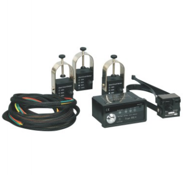
The JY EKL-4 (SJWL-EKL-4) Panel Type Fault Indicator is a centralized fault monitoring device designed specifically for 10kV medium-voltage power distribution systems. It consists of a panel host, line fault sensors, and connecting wires. It can be installed on the panel of equipment such as ring main units, prefabricated substations, and cable branch boxes to monitor short-circuit and grounding faults of multiple cable lines in real time. When a fault occurs, the faulty line is displayed intuitively through LED indicators on the panel. It also has extended functions such as fault memory and remote communication. It is a key device for improving the efficiency of fault diagnosis and the level of intelligent operation and maintenance of power distribution systems.
II. Product Characteristics
1. Fault detection and indication performance
- Multi-line centralized monitoring : It can simultaneously monitor short circuit and grounding faults of 3 cable lines, and is compatible with three-phase four-wire or three-phase three-wire power distribution systems. It has a high fault identification accuracy and a low false alarm rate.
- Dual fault detection : The external fault sensor detects sudden changes in short-circuit current and zero-sequence current. Both short-circuit and ground faults can trigger an indication, and the fault type can be distinguished and displayed.
- Intuitive and centralized indication : The main panel uses LED indicator lights to display the fault status of each line. When a fault is triggered, the corresponding line indicator light stays on, making it easy for maintenance personnel to quickly locate the faulty line on the equipment panel.
- Fault memory and reset : After the line fault is cleared, the indicator can be automatically reset, or the fault memory can be cleared by manually resetting the button. Fault records can be stored for a long time, which is convenient for fault tracing.
- Extended communication functions : Optional RS485/Modbus communication interface can be added to upload fault information to the background monitoring system, realize remote fault monitoring and alarm, and improve the level of intelligent operation and maintenance.
2. Structural and Installation Characteristics
- Split-type modular design : It consists of a panel host, external fault sensors, and connecting cables. The sensors are snap-on installed on the cable line, and the host is installed on the equipment panel. The installation is convenient and can be carried out without power interruption.
- Fully sealed sensor structure : The fault sensor housing is made of high-strength engineering plastic with an IP67 protection rating, making it moisture-proof, waterproof, dirt-proof, and salt spray-proof, and capable of long-term stable operation in harsh environments such as outdoors, humidity, and dust.
- Low power consumption and long lifespan design : The panel host uses low power electronic components and can be powered by the internal power supply or the built-in battery. The sensor adopts a passive design and has a service life of more than 10 years, requiring no frequent maintenance.
- Strong anti-interference performance : Built-in anti-interference circuit can effectively resist line induced electric and electromagnetic interference, avoid malfunctions, improve the reliability of fault detection, and is suitable for strong electromagnetic interference scenarios such as ring network cabinets and box-type substations.
3. Environmental and Weather Resistance
- Strong wide temperature adaptability : It can adapt to a wide temperature range of -40℃ to +85℃. The electronic components are stable under high and low temperatures, with no risk of crashes or malfunctions. It is suitable for various outdoor and indoor scenarios.
- Excellent moisture and dirt resistance : The sensor has a fully sealed housing structure to prevent moisture and dust from entering; the panel host adopts a dustproof design, which is suitable for the dusty environment inside the power distribution equipment.
- Excellent anti-aging performance : The outer shell is made of UV-resistant and aging-resistant engineering plastics, which can withstand long-term outdoor use without cracking or embrittlement. The internal components of the equipment have excellent anti-aging performance and a service life of more than 10 years.
III. Technical Parameters
| Parameter categories | project | Technical indicators |
| Applicable line parameters | Applicable system voltage (Un) | 10kV |
| Applicable cable outer diameter | 16~30mm (other sizes can be customized) | |
| Applicable line current | 10~630A | |
| Fault detection parameters | Number of monitored lines | Route 3 |
| Short circuit fault operating current | 200~1000A (adjustable) | |
| Ground fault operating current | 10~100A (adjustable) | |
| Fault response time | ≤0.1s | |
| Reset method | Automatic Reset / Manual Reset | |
| Instruction method | Centralized display of LED indicator lights on the panel | |
| Electrical parameters | working power supply | AC/DC 220V (powered by the device’s mains) / Powered by the built-in lithium battery |
| Static power consumption | ≤1W | |
| Communication interface | Optional RS485/Modbus (extended functionality) | |
| Structural and environmental parameters | Main material | High-strength engineering plastics (sensor/main unit housing), metal (buckles) |
| Protection level | Sensor IP67, host IP40 | |
| Applicable altitude | ≤2000m (Customization available for high altitudes) | |
| Ambient temperature | -40℃/ +85℃ (operating temperature), -40℃/ +70℃ (storage temperature) | |
| relative humidity | ≤100% (no condensation) | |
| Seismic resistance level | Level 8 | |
| Implementation Standards | DL/T 1073 “Technical Conditions for Fault Indicators in Distribution Networks”, GB/T 17626 “Electromagnetic Compatibility Testing and Measurement Technology”, and GB/T 11022 “Common Technical Requirements for High-Voltage Switchgear and Controlgear Standards” |
IV. Scope of Application
- Applicable voltage level : 10kV AC medium voltage power distribution system, compatible with cable lines with a maximum operating voltage of 12kV.
- Applicable equipment scenarios :
- On the panels of power distribution equipment such as 10kV ring main units, prefabricated substations, cable branch boxes, and American-style prefabricated substations, short circuit and grounding faults of multiple cable lines are centrally monitored.
- Urban power distribution cable lines, power distribution systems for industrial and mining enterprises, and power distribution lines for new energy (photovoltaic/wind power) substations;
- Centralized monitoring of faults in power distribution equipment in various scenarios, including indoor power distribution rooms, underground utility tunnels, and cable tunnels.
- Function and Purpose : Centrally monitor and indicate the location of short circuits and grounding faults in multiple cable lines of 10kV power distribution equipment, helping maintenance personnel to quickly troubleshoot faults, shorten fault handling time, and improve the power supply reliability of the power distribution system; Extended communication functions can realize remote fault monitoring and alarm, and assist in the intelligent operation and maintenance of the power distribution system.
V. Usage Conditions
1. Normal operating conditions
- Altitude: ≤2000m;
- Ambient temperature: -40℃~+85℃; equipment operating temperature complies with relevant standards.
- Relative humidity: ≤100% (no condensation);
- Environmental conditions: No corrosive gases, no flammable or explosive media, no severe vibration or impact;
- Installation method: The sensor is snap-on and installed on the cable line, while the main unit is panel-mounted and installed on the power distribution equipment panel. The installation location should be convenient for observing the indication status and maintenance.
2. Special usage conditions (customization required)
- The altitude exceeds 2000m;
- The ambient temperature exceeds the range of -40℃ to +85℃;
- Severely polluted, salt spray, and chemically corrosive environments;
- Strong electromagnetic interference conditions;
- Non-standard cable outer diameter specifications;
- Monitoring the number of lines and customizing communication functions to meet specific needs.
VI. Installation and Maintenance
1. Installation Requirements
- Before installation, inspect the product appearance for cracks and damage, and ensure that the sensors, main unit, and connecting cables are intact. Test the fault indication function to ensure it is normal, and the indicator lights should illuminate correctly when there is no fault.
- Clean the surface of the cable line to remove oil, dust, and foreign objects. Install the fault sensor on the cable line, ensuring that the clip is securely installed and that the sensor makes good contact with the cable. Install one sensor for each line.
- Install the panel host on the power distribution equipment panel, fix it firmly, and ensure that the installation position is convenient for observing the status of the indicator lights.
- Use a dedicated connecting cable to connect the sensor to the corresponding interface on the panel host, ensuring that the wiring is secure and there are no loose connections or poor contacts.
- After installation, power on and test to simulate short circuit and grounding faults. Check if the corresponding indicator lights are lit normally, if the automatic reset function is normal, and if the communication function (if any) is normal.
2. Maintenance Requirements
- Regularly inspect the appearance of the sensors and main unit to ensure there are no cracks, damage, or dirt accumulation, that the installation is secure and not loose, and that the connecting wires are not aged or damaged.
- Regularly test the fault indication function. When a fault is triggered, the corresponding line indicator light should light up normally. After the fault is cleared, the indicator light should automatically reset. The manual reset function should also work normally.
- Clean the sensor and main unit surfaces to remove dust and dirt, keep the casing dry and clean, and avoid corrosion from oil and chemicals.
- Check if the host power supply is normal, if the communication function (if present) is stable, and if the data upload is normal.
- When equipment malfunctions, fails to indicate, or experiences communication abnormalities, the cause must be investigated and repaired immediately. If repair is not possible, the equipment must be replaced. Operation with a malfunction is strictly prohibited.
VII. Precautions
- The product must be installed, debugged, and maintained by professional electrical personnel with medium-voltage power distribution construction qualifications. Operation by non-professional personnel is strictly prohibited.
- The product must be used with cables and power distribution equipment of the corresponding specifications. It is strictly forbidden to install it on lines of different voltage levels, otherwise it will lead to equipment damage and safety accidents.
- The equipment must not be disassembled or modified without authorization, otherwise the warranty and safety guarantee will be lost. It is strictly forbidden to use non-specialized tools to forcibly disassemble it.
- Sensors should be installed away from cable joints, bends, and sources of strong electromagnetic interference. The main unit should be installed away from heat-generating components to avoid high temperatures affecting equipment performance.
- When storing, place in a dry, ventilated, and cool environment, avoiding direct sunlight, high temperature, humidity, and pressure. Do not allow it to come into contact with sharp objects, which could damage the outer casing and connecting wires.
- The fault indicator is only a fault monitoring device and cannot replace the relay protection device. Line faults still need to be handled in accordance with the power distribution safety regulations.
VIII. Model Description
| Model Identification | meaning |
| JY | Product series code |
| EKL-4 / SJWL-EKL-4 | Panel-type fault indicator series code |
| Panel Type Fault Indicator | Panel-mounted fault indicator for centralized fault monitoring of multiple cable lines in 10kV power distribution equipment. |
IX. Implementation Standards and Certification
- National standards: DL/T 1073 Technical conditions for fault indicators in distribution networks, GB/T 17626 Electromagnetic compatibility testing and measurement techniques, GB/T 11022 Common technical requirements for high voltage switchgear and controlgear standards;
- The product has passed the type test of the National Power Equipment Quality Supervision and Inspection Center and meets the national power industry standards.
X. After-sales service
- Product warranty period: 18 months from the date of manufacture, or 12 months from the date of commissioning (whichever comes first).
- During the warranty period, products will be repaired or replaced free of charge if quality issues arise.
- We provide technical support, installation guidance, and customized services (special cable outer diameter, number of monitoring lines, and communication function adaptation).
Document Description
The technical parameters in this manual are based on standard operating conditions. Special operating conditions need to be customized according to actual needs. The final specifications shall be subject to the product technical agreement and type test report.
Appendix: Product outline diagram