Product Overview
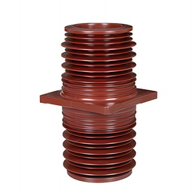
The 35kV-260 (Height 588) (High-Altitude Type) Bushing is a 35 kV high-altitude epoxy resin wall bushing manufactured as an integrated structure using the APG process. It is specially designed for high-altitude environments and is mainly used in 35 kV high-voltage switchgear, substation distribution equipment, and related electrical systems.
The bushing provides electrical insulation and mechanical support where conductive components pass through switchgear enclosures or walls. Its reinforced insulation design helps maintain reliable dielectric performance and stable operation under low atmospheric pressure at high altitudes.
Technical Specifications
| Parameter | Specification |
|---|---|
| Rated Voltage | 40.5 kV, suitable for 35 kV systems |
| Rated Frequency | 50 Hz |
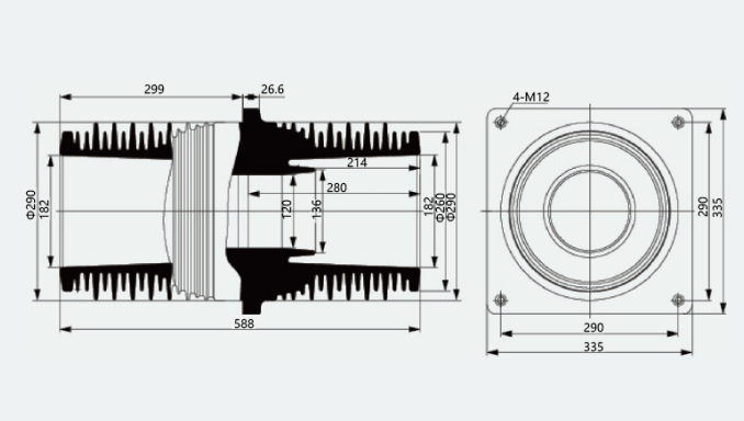
| Mounting Centre Distance / Flange Dimensions | 260 × 260 mm |
| Overall Height | 588 mm |
| Creepage Distance | ≥1,020 mm, optimized for high-altitude applications |
| Power-Frequency Dry Withstand Voltage | ≥95 kV for 1 minute |
| Power-Frequency Wet Withstand Voltage | ≥80 kV for 1 minute |
| Lightning Impulse Withstand Voltage | ≥185 kV peak |
| Partial Discharge | ≤5 pC at 1.1 times the rated phase voltage |
| Dielectric Loss Factor (tan δ) | ≤0.005 at 1.1 times the rated phase voltage |
| Rated Bending Failure Load | ≥8 kN |
| Applicable Altitude | ≤3,000 m |
| Ambient Temperature Range | -40°C to +40°C |
| Material | High-temperature-cured, halogen-free epoxy resin |
Product Features
High-Altitude Insulation Design
The insulation structure is optimized for low atmospheric pressure at altitudes of up to 3,000 m. The increased number of sheds and extended creepage distance compensate for the reduction in dielectric strength at high altitudes and help reduce the risk of electrical flashover.
High Insulation Reliability
The bushing is integrally cast from epoxy resin, producing a dense structure without bubbles or delamination. It provides excellent dielectric performance and extremely low partial discharge, allowing reliable long-term operation under high-voltage conditions.
Weather and Pollution Resistance
The shed structure provides good hydrophobicity and self-cleaning performance. Its resistance to electrical tracking and erosion complies with the applicable requirements of IEC 60587, making the product suitable for dusty high-altitude environments with significant temperature variations.
Excellent Mechanical Strength
The integrated structure provides reliable impact and bending resistance. It can withstand the electrodynamic forces generated by busbars under short-circuit conditions, as well as long-term mechanical stress during operation.
Low Maintenance Requirements
The epoxy resin material provides good resistance to ageing and corrosion. No regular application of anti-pollution coatings is required, helping reduce maintenance requirements and operating costs.
Convenient Installation
The standard 260 × 260 mm flange dimensions are compatible with mainstream 35 kV switchgear designs, allowing quick installation and connection.
Applications
Applicable Systems
Suitable for AC power-frequency systems with a rated voltage of 35 kV and a maximum system voltage of 40.5 kV.
Applicable Equipment
The product can be used in:
- 35 kV high-voltage switchgear
- Box-type substations
- Ring main units
- Substation distribution equipment
- Busbar and conductive bar wall-passage applications
- Busbar passage through switchgear enclosures
It functions as an insulating support where busbars or other conductive components pass through walls, cabinet panels, or grounded partitions.
Applicable Environments
Suitable for high-altitude areas up to 3,000 m and for indoor or semi-outdoor environments without severe vibration or obvious corrosive gases.
Pollution Level
Suitable for Pollution Levels II to III. Reinforced versions can be customized for more heavily polluted environments.
Operating Conditions
Environmental Conditions
- Installation altitude: ≤3,000 m. Special customization is required above 3,000 m.
- Ambient temperature: -40°C to +40°C.
- Daily average ambient temperature: no more than +35°C.
- Monthly average relative humidity: no more than 90% at 25°C.
- Long-term condensation and frost formation should be avoided.
- The atmosphere should be free from flammable, explosive, corrosive, or conductive dust.
- Severe salt spray and chemical pollution are not permitted under standard operating conditions.
- The installation position should be free from severe vibration and impact.
- Vibration frequency: ≤100 Hz.
- Vibration acceleration: ≤10 m/s².
Electrical Conditions
- System frequency: 48–52 Hz.
- Continuous operating voltage: ≤1.1 times the rated phase voltage.
- Short-circuit withstand capability: capable of withstanding the specified short-time withstand current and peak withstand current of the system, subject to the selected busbar specifications.
Installation Requirements
- The product may be installed vertically or horizontally.
- The flange must fit closely against the switchgear enclosure or wall to provide reliable sealing.
- The connection between the conductive bar and the internal conductor of the bushing must be secure to prevent localized overheating.
- Indoor installations should provide adequate ventilation.
- A protective rain cover is recommended for semi-outdoor installations and is available as an option.
Applicable Standards
- GB/T 4109-2019, Technical Specifications for High-Voltage Bushings
- IEC 60137:2017, Insulated Bushings for Alternating Voltages Above 1,000 V
- GB/T 20840.1-2010, Instrument Transformers—Part 1: General Requirements
- DL/T 853-2015, Insulating Tools for Live Working, referenced for applicable insulation performance requirements
Precautions
- Before installation, inspect the product to ensure that there are no cracks, damage, bubbles, or visible deformation and that all markings are clear and complete.
- Avoid severe impact during handling and installation to prevent damage to the sheds or internal insulation structure.
- Do not drill, cut, grind, or otherwise machine the product surface, as this may damage the insulating structure.
- If surface tracking, abnormal noise, or excessive temperature rise is detected during operation, immediately de-energize and inspect the equipment.
- The warranty period is 12 months from the date of manufacture. Products damaged by manufacturing defects rather than improper handling may be replaced free of charge during the warranty period.
Ordering Information
- Model example: 35kV-260, 588 mm High, High-Altitude Type
- Please specify the installation orientation, either vertical or horizontal.
- Confirm the dimensions and specifications of the conductive bar.
- Indicate whether a protective rain cover is required.
- Specify any special environmental pollution requirements.
- Customized overall heights, creepage distances, and flange dimensions are available according to project requirements.