Product Overview
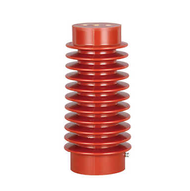
The CG5-24Q Series Indoor High-Voltage Presence Indicating Device Sensor is a high-voltage insulating component designed according to the capacitive voltage-divider principle. It is mainly used to indicate the energized status of high-voltage circuits and provide forced interlocking, helping ensure the safe operation of high-voltage equipment.
The product is manufactured using an integrated epoxy resin casting process. It also provides the insulation and mechanical support functions of a post insulator and can replace a conventional post insulator in compatible applications. It is widely used in 24 kV indoor high-voltage distribution systems.
Product Features
Main Performance Features
- Integrated indication and interlocking functions:
The sensor provides real-time indication of the energized status of the high-voltage circuit and forced interlocking of the switchgear access door, offering reliable protection against incorrect operation. The voltage indication and interlocking functions are controlled by the same high-voltage signal but operate through independent circuits. Even if the indication or control circuit develops a fault, the electromagnetic lock remains locked while the high-voltage circuit is energized, providing enhanced operational safety. - Excellent insulation performance:
The epoxy resin cast structure provides a creepage distance suitable for 24 kV operating conditions, low partial discharge, strong resistance to arc ageing, and stable long-term insulation performance. - High mechanical strength:
The one-piece cast structure provides excellent resistance to impact and torsional stress, making it suitable for complex installation conditions inside high-voltage switchgear. - Wide compatibility:
The sensor is compatible with various indoor high-voltage presence indicators, including DXN series devices, and can be interlocked with electromagnetic locks, earthing switches, disconnectors, and other equipment.
Materials and Manufacturing Process
- Housing material: Epoxy resin manufactured using the APG casting process, providing a high insulation level and reliable environmental resistance.
- Internal structure: Integrated capacitive sensing rod for accurate voltage sampling and stable signal transmission.
- Surface design: Shed-type insulating profile that increases creepage distance and improves resistance to pollution flashover.
Technical Specifications
| Parameter | Specification | Remarks |
|---|---|---|
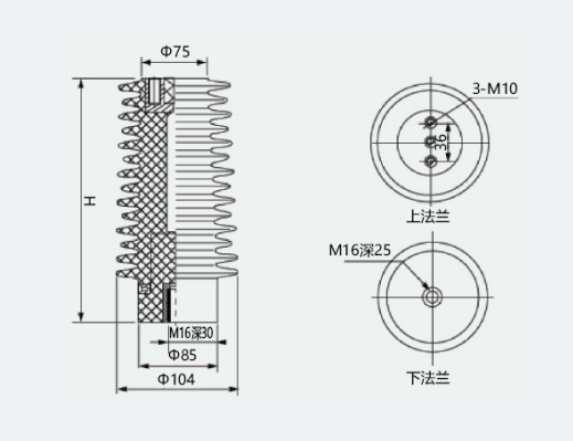
| Models | CG5-24Q/110×190, CG5-24Q/110×210, CG5-24Q/110×225 | Suffix indicates diameter × height in mm |
| Rated Voltage | 24 kV | Suitable for 20–24 kV indoor high-voltage systems |
| Rated Lightning Impulse Withstand Voltage | 125 kV full wave | Peak withstand level |
| Power-Frequency Withstand Voltage | 95 kV for 1 minute | RMS value |
| Interlocking Trigger Condition | Forced interlocking when the voltage of any phase reaches 65%–100% of the rated phase voltage | Q-type interlocking function |
| Indication Trigger Condition | Indicator illuminates when the phase voltage reaches 15%–65% of the rated phase voltage | Real-time voltage presence indication |
| Overall Dimensions | 110 × 190 mm, 110 × 210 mm, or 110 × 225 mm | Diameter × height |
| Material | APG-cast epoxy resin | — |
| Output Type | Relay interlocking contact, normally open or normally closed optional | Suitable for electromagnetic lock interlocking |
| Applicable Frequency | 50 Hz | Suitable for power-frequency systems |
Applications
Main Application Areas
- High-voltage switchgear:
Indoor withdrawable switchgear, ring main units, gas-insulated switchgear, and other high-voltage switching equipment. - Power distribution equipment:
Used with vacuum circuit breakers, earthing switches, disconnectors, and related components. - Power systems:
Suitable for substations, distribution rooms, industrial facilities, mining enterprises, and other high-voltage power supply systems. - Renewable energy systems:
Suitable for indoor high-voltage distribution equipment in photovoltaic and wind power grid-connected systems.
Compatible Equipment
The sensor can be used with various indoor high-voltage presence indicators, such as DXN-Q models, electromagnetic locks, high-voltage sensors, and insulators.
It integrates the following functions:
- Voltage presence indication
- Forced electrical interlocking
- Insulating support
- Mechanical support
- Safety protection
Operating Conditions
Environmental Conditions
- Ambient temperature: -25°C to +40°C. Versions suitable for -35°C to +40°C are available for special regions.
- Installation altitude: no more than 1,000 m. For installations above 1,000 m, the insulation performance must be evaluated according to applicable high-voltage insulation requirements.
- Daily average relative humidity: no more than 95% RH.
- Monthly average relative humidity: no more than 90% RH.
- The installation environment should be free from severe pollution, flammable or explosive gases, chemically corrosive substances, and salt spray.
- Direct sunlight should be avoided.
Installation Conditions
- The product should be installed inside indoor high-voltage switchgear on a flat and stable mounting surface.
- Flange or bolt mounting may be used. The mounting holes must correspond to the embedded mounting structure of the product.
- The terminal of the capacitive sensing rod must be reliably connected to the high-voltage circuit.
- The interlocking contact wiring must comply with electrical control requirements. Loose, incorrect, or reversed connections must be avoided.
Operating Conditions
- The product must operate within its rated voltage of 24 kV. Operation above the rated voltage is prohibited.
- Inspection is recommended every 6 to 12 months during normal operation.
- The inspection should focus on:
- Cleanliness of the insulating surface
- Tightness of electrical connections
- Effectiveness of the interlocking function
- Condition of the sheds
- Integrity of the epoxy resin body
- The product must not be removed or touched while energized.
- Oil, dust, and other contaminants must not be allowed to accumulate on the insulating surface.
Installation and Maintenance
Installation Procedure
- Clean the mounting surface and remove oil, dust, and foreign materials.
- Install the sensor vertically in the designated switchgear position and tighten the mounting bolts evenly.
- Connect the high-voltage circuit to the capacitive sensing rod and ensure reliable electrical contact.
- Connect the interlocking contact to the electromagnetic lock and voltage presence indicator circuit. Check the wiring and polarity carefully.
- Conduct an energization test to confirm that the voltage indicator and interlocking contact operate correctly.
Maintenance Requirements
- Routine inspection:
Check the insulating surface for cracks, damage, electrical tracking, or contamination. Confirm that the wiring terminals are secure and that the sheds are clean. - Cleaning:
Clean surface contamination using a dry, soft cloth. Do not wash the product directly with water. - Troubleshooting:
- No voltage indication: Check whether the high-voltage connection is loose or disconnected and whether the capacitive sensing rod is damaged.
- Interlocking failure: Check the interlocking contacts, wiring connections, and relay. Replace faulty components as required.
- Insulation abnormality: If electrical tracking, surface cracks, or other insulation damage is found, replace the sensor immediately.
Precautions
- This product is a high-voltage equipment component. Installation and maintenance must be carried out by qualified electrical personnel in strict accordance with high-voltage safety procedures.
- Do not drill, cut, grind, or otherwise modify the product surface. Such modification may damage the epoxy resin cast structure and cause insulation failure.
- Store the product in a dry and ventilated warehouse. Protect it from moisture, impact, and mechanical damage.
- When stored in its original undamaged packaging under suitable conditions, the storage period should be no less than 12 months.
- Product selection must match the switchgear voltage level and installation dimensions.
- For special dimensions, output contacts, or wiring configurations, confirm all technical parameters with the manufacturer before production.
Quality Assurance
The product is manufactured under an ISO 9001 quality management system.
Before delivery, each product undergoes comprehensive testing, including:
- Power-frequency withstand voltage testing
- Partial discharge testing
- Interlocking operation testing
- Insulation performance inspection
- Visual and dimensional inspection
These tests help ensure that the product meets the specified performance requirements.