Product Overview
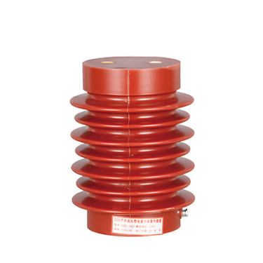
The CG5-10Q Series Indoor High-Voltage Presence Indicator Sensor for Earthing Switches is a core insulating and sensing component designed for 10 kV indoor high-voltage switchgear assemblies, including high-voltage switchgear and ring main units.
The product is integrally cast from epoxy resin and provides high electrical insulation, high mechanical strength, and excellent environmental resistance. It also incorporates a voltage presence sensing function and can be used with a high-voltage presence indicator to monitor the energized status of a high-voltage circuit in real time.
As a dedicated insulating sensor for earthing switch applications, it provides reliable protection for the safe operation and maintenance of high-voltage equipment.
Model Description
| Model Code | Description |
|---|---|
| CG5 | Indoor high-voltage presence indicator sensor with epoxy resin cast construction |
| 10Q | Rated voltage of 10 kV; Q indicates a reinforced or indoor configuration |
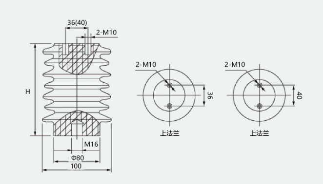
| 100×140 (145, 150, 170) | Mounting dimensions: 100 mm mounting-hole centre distance; 140, 145, 150, or 170 mm overall height, selectable according to the switchgear structure |
Product Features
Excellent Insulation Performance
The sensor is manufactured through integrated vacuum casting using high-quality epoxy resin. Its dense structure is free from bubbles and impurities, providing high dielectric strength.
It can withstand the long-term operating voltage, lightning impulse voltage, and power-frequency withstand voltage of a 10 kV system. It meets the applicable requirements of GB/T 19519 and helps prevent surface flashover and electrical breakdown.
High Sensing Accuracy and Reliability
The built-in high-precision capacitive sensing structure accurately detects the energized signal of the high-voltage circuit.
When connected to a high-voltage presence indicator, it provides stable voltage status indication without signal drift, false alarms, or missed signals. This supports reliable energized-circuit interlocking.
High Mechanical Strength and Stable Structure
The one-piece cast structure provides high mechanical strength and can withstand the mechanical stress generated during earthing switch operation, as well as vibration and impact during switchgear transportation and installation.
The product is resistant to cracking and deformation and provides a long service life.
Strong Environmental Resistance
The epoxy resin material provides excellent resistance to ageing, heat and humidity, ozone, and corona discharge.
It can operate reliably for extended periods in complex indoor environments and provides good resistance to contamination, making it suitable for various indoor high-voltage power distribution applications.
Convenient Installation and Wide Compatibility
Standard mounting dimensions of 100 × 140, 100 × 145, 100 × 150, and 100 × 170 mm allow the sensor to fit the earthing switch mounting positions of various 10 kV indoor high-voltage switchgear and ring main units.
No additional modification is normally required, simplifying installation and maintenance.
High Safety Protection
The fully enclosed insulating structure effectively isolates high-voltage live parts and helps prevent electric shock and phase-to-phase short circuits.
It also meets the insulation and isolation requirements of earthing switches, improving the overall safety protection level of high-voltage equipment.
Technical Specifications
| Parameter | Specification |
|---|---|
| Rated Voltage (Un) | 10 kV |
| Maximum Operating Voltage (Um) | 12 kV |
| Rated Frequency | 50 Hz |
| Power-Frequency Withstand Voltage | 42 kV for 1 minute, phase-to-earth and phase-to-phase |
| Lightning Impulse Withstand Voltage | 75 kV peak, phase-to-earth and phase-to-phase |
| Sensing Capacitance | 10–30 pF, customizable according to the matched voltage presence indicator |
| Dielectric Loss Factor (tan δ) | ≤0.002 at rated voltage and 50 Hz |
| Partial Discharge | ≤5 pC at 1.1 Um/√3 |
| Creepage Distance | ≥230 mm, meeting the pollution requirements of 10 kV systems |
| Mechanical Life | ≥10,000 earthing switch operating cycles |
| Insulating Material | Epoxy resin, UL94 V-0 flame-retardant rating |
| Ambient Temperature | -25°C to +40°C |
| Installation Altitude | ≤1,000 m; high-altitude versions available |
| Relative Humidity | Daily average ≤95%; monthly average ≤90% |
| Mounting Dimensions | 100 mm mounting-hole centre distance; overall height of 140, 145, 150, or 170 mm |
| Colour | Standard red; other colours available |
Applications
Applicable Voltage Level
Suitable for 10 kV and 12 kV indoor high-voltage power distribution systems.
Applicable Equipment
The sensor is suitable for various indoor high-voltage switchgear assemblies, including:
- KYN28 switchgear
- XGN15 switchgear
- HXGN switchgear
- Ring main units
- Box-type substations
- High-voltage gas-insulated switchgear
- Other complete indoor high-voltage equipment
It is specifically designed for use with earthing switches as an insulating support and voltage presence sensing component.
Applicable Industries and Locations
- Indoor high-voltage distribution equipment in substations and distribution rooms
- High-voltage power systems in industrial and mining enterprises
- Rail transit power distribution systems
- Photovoltaic and wind power booster stations
- Other indoor high-voltage switchgear requiring voltage presence indication and energized-circuit interlocking
Main Functions
- Real-time monitoring and indication of the energized status of high-voltage circuits
- Insulating isolation and support for earthing switches
- Energized-circuit interlocking
- Prevention of operating an earthing switch while the circuit is energized
- Prevention of accidental access to energized compartments
Operating Conditions
Normal Operating Conditions
- Ambient temperature: -25°C to +40°C, with a daily average temperature not exceeding +35°C.
- Installation altitude: no more than 1,000 m.
- Daily average relative humidity: no more than 95%.
- Monthly average relative humidity: no more than 90%.
- Indoor installation in locations free from severe vibration, explosion hazards, corrosive gases, serious contamination, rain, and snow.
- The sensor should be installed vertically at the earthing switch position. The inclination of the mounting surface from the vertical plane should not exceed 5°.
- The operating power supply of the matched voltage presence indicator may be AC/DC 220 V, 110 V, or another conventional specification, depending on the matched device.
Special Operating Conditions
Customized products are required for:
- Installation altitudes above 1,000 m. Altitude correction should be carried out according to GB/T 11022, and a high-altitude version should be selected.
- Ambient temperatures outside the range of -25°C to +40°C.
- Environments with severe pollution, high heat and humidity, salt spray, or condensation.
- Locations involving severe vibration or mechanical impact.
Installation and Maintenance Requirements
Installation Requirements
- Inspect the product before installation. Confirm that the surface is free from cracks, damage, bubbles, and deformation and that the nameplate information is complete and clearly visible.
- Install the sensor vertically at the earthing switch position according to the switchgear installation drawings. Ensure that it is securely fixed and that the bolt-tightening torque meets the specified requirements.
- Correctly connect the sensor terminal to the high-voltage presence indicator. Ensure that the wiring is secure and properly insulated.
- After installation, conduct an insulation resistance test and a power-frequency withstand voltage test. The product may be put into operation only after the test results are confirmed as acceptable.
- Avoid impact and compression during installation to prevent cracking of the epoxy resin body.
Maintenance Requirements
- Regularly inspect the product for cracks, damage, contamination, loose wiring terminals, and abnormal temperature rise.
- Conduct regular functional checks together with the voltage presence indicator to confirm that the voltage indication and interlocking functions operate correctly.
- Regularly conduct an insulation resistance test using a 2,500 V megohmmeter. The insulation resistance should be at least 1,000 MΩ. A power-frequency withstand voltage test should also be performed as required.
- Clean contamination from the product surface and keep the insulating surface clean and dry to prevent surface flashover.
- Replace the product immediately if cracking, damage, or reduced insulation performance is detected. Continued use of a defective sensor is prohibited.
Applicable Standards
The product is designed, manufactured, and tested according to the following standards:
- GB/T 19519, Insulator Strings and Insulator Sets for Overhead Lines with a Nominal Voltage Above 1,000 V—AC Power-Frequency Dry and Wet Test Methods
- GB/T 11022, Common Specifications for High-Voltage Switchgear and Controlgear Standards
- DL/T 538, Technical Specifications for High-Voltage Presence Indicators
- JB/T 10685, Sensors for High-Voltage Presence Indicating Systems
- IEC 60660, Insulation Coordination for High-Voltage Switchgear and Controlgear
Selection Guide
| Model | Overall Height | Recommended Application |
|---|---|---|
| CG5-10Q/100×140 | 140 mm | Compact switchgear and ring main units with limited installation space |
| CG5-10Q/100×145 | 145 mm | Standard 10 kV indoor switchgear and ring main units |
| CG5-10Q/100×150 | 150 mm | Reinforced-insulation switchgear and locations with moderately higher pollution levels |
| CG5-10Q/100×170 | 170 mm | Special applications requiring higher insulation performance and a longer creepage distance |
The appropriate model should be selected according to the switchgear structure, available installation space, and insulation requirements. The capacitance matching requirements of the corresponding high-voltage presence indicator must also be confirmed.
Precautions
- This product is a high-voltage insulating component. Installation, removal, and maintenance while energized are strictly prohibited. All work must be carried out only after the equipment has been de-energized, tested for the absence of voltage, and grounded.
- Installation, commissioning, and maintenance must be performed by qualified electrical personnel. Operation by unauthorized personnel is prohibited.
- Protect the product from impact, compression, and moisture during transportation and storage. Store it in a dry, ventilated environment free from corrosive gases.
- Do not force the product into installation if its model or technical parameters do not match the on-site requirements. Contact the manufacturer for a compatible replacement.
- The product is a component of complete electrical equipment and must be used with a qualified high-voltage presence indicator and earthing switch to ensure the overall safety of the system.
After-Sales Service
- The warranty period is 12 months from the date of manufacture or 12 months from the date of commissioning, whichever occurs first.
- During the warranty period, products that fail due to manufacturing or quality defects will be repaired or replaced free of charge.
- Technical support, installation guidance, and on-site commissioning services are available.
- Lifetime maintenance support is provided. Chargeable repair services are available after the warranty period.
Appendix: Product Outline Drawing