HY(YH)5W-3~6kV series surge arresters
I. Product Overview
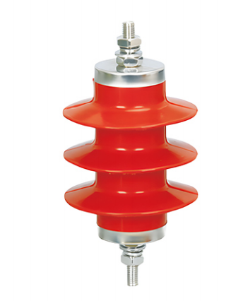
The HY (YH) series surge arresters are gapless metal oxide surge arresters designed specifically for 3~6kV AC systems. They cover three special scenarios: rotating motors, motor neutral points, and capacitors. They are encapsulated with a silicone rubber composite jacket and have excellent overvoltage protection performance. They can effectively limit lightning overvoltage and switching overvoltage and protect the insulation of motors, capacitors and other equipment from damage.
II. Product Characteristics
1. Electrical and protective performance
- It adopts high-performance zinc oxide resistors, which have excellent volt-ampere characteristics, low residual voltage and large current capacity, and can effectively limit the lightning overvoltage and switching overvoltage of the corresponding system, protecting the equipment insulation from damage.
- It has a fast response speed and can act instantly when an overvoltage occurs, promptly dissipating overvoltage energy, preventing overvoltage from entering the equipment, and providing stable and reliable protection performance.
- It exhibits excellent nonlinear voltage-current characteristics, with minimal leakage current and low power consumption under normal operating voltage; it conducts rapidly under overvoltage and automatically returns to its insulating state after dissipating energy, requiring no maintenance.
2. Structural and Safety Features
- It adopts an integral silicone rubber composite jacket, which is seamless and air-gap-free, and has excellent sealing performance. It can effectively prevent moisture and dirt from entering the interior and avoid damage to the resistor element due to moisture.
- The integrated modular structure design provides high mechanical strength, impact and vibration resistance, and the ability to withstand mechanical stress during transportation, installation, and operation without the risk of deformation or breakage.
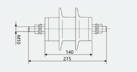
- It comes with built-in threaded terminals (M10/M12 optional), making installation convenient. It can be directly connected in series between the device and the ground without the need for additional auxiliary equipment, and is suitable for a variety of installation scenarios.
- With its gapless design, there is no follow current during operation, eliminating the risk of explosion and fire caused by power frequency follow current, thus ensuring high safety.
3. Environmental and Weather Resistance
- With excellent weather resistance, it can adapt to a wide temperature range of -40℃ to +90℃. The elasticity and insulation performance of the silicone rubber jacket do not decrease under high and low temperatures, and there is no risk of cracking or embrittlement. It is suitable for various outdoor and indoor scenarios.
- It is moisture-proof, waterproof, stain-proof, and salt spray-proof, and can operate stably for a long time in harsh environments such as humid, dusty, and salt spray conditions. It is not afraid of rain or condensation corrosion. The silicone rubber surface has strong hydrophobicity, which can effectively prevent surface flashover.
- It is resistant to aging, ultraviolet rays, and ozone corrosion, with a service life of over 20 years. It requires no maintenance and reduces subsequent operation and maintenance costs.
4. Mechanical and Adaptation Characteristics
- It has high mechanical strength, is impact and vibration resistant, and can withstand the mechanical stress generated by equipment operation vibration and lightning current impact. There is no risk of deformation or damage, and the seismic resistance level reaches level 8.
- It is compatible with 3~6kV AC systems and has special models designed for different scenarios such as rotating motors, motor neutral points, and capacitors, making it highly versatile.
- Small in size and light in weight, it is easy to install and can be directly fixed to the equipment junction box or power distribution equipment without complicated installation procedures.
III. Technical Parameters
| Location of use | Surge arrester model | Surge arrester rated voltage (kV) | System nominal voltage (kV) | Continuous operating voltage (kV) | DC 1mA reference voltage (kV) | Maximum residual voltage (kV, peak value) | 2000μs square wave current capacity (A) | 4/10 High current withstand capability (kA) | Leakage current (μA) at 0.75 times the DC reference voltage | Ionization creepage distance (mm) | External dimensions (mm) | Terminal block specifications |
| Rotary motor | HY(YH)2.5W-4/9.5 | 4 | 3.15* | 3.2 | ≥5.7 | Steep wave: 10.7, Lightning: 9.5, Operation: 7.6 | 200 | 65 | ≤50 | 115 | Φ102×167 | M10 |
| Rotary motor | HY(YH)2.5W-8/18.7 | 8 | 6.3* | 6.3 | ≥11.2 | Steep wave: 21.0, Lightning: 18.7, Operation: 15.0 | 200 | 65 | ≤50 | 225 | Φ198×190 | M10 |
| motor neutral point | HY(YH)1.5W-2.4/6 | 2.4 | 3.15* | 1.9 | ≥3.4 | Raiden: 6.0, Operation: 5.0 | 200 | 65 | ≤50 | 75 | Φ105×224 | M12 |
| motor neutral point | HY(YH)1.5W-4.8/12 | 4.8 | 6.3* | 3.8 | ≥6.8 | Lightning: 12.0, Operation: 10.50 | 400 | 65 | ≤50 | 155 | Φ105×224 | M12 |
| capacitor | HY(YH)5WR-3.(5)/13.5 | 3.8(5) | 3* | 2(4) | ≥7.2 | Lightning: 13.5, Action: 10.5 | 400 | 65 | ≤50 | 155 | Φ105×224 | M12 |
| capacitor | HY(YH)5WR-7.6(10)/27.0 | 7.6(8) | 6* | 4(8) | ≥14.4 | Lightning: 27.0, Actions: 20.8 | 400 | 65 | ≤50 | 225 | Φ198×190 | M10 |
Note: The nominal voltage of the system marked with “ ” is the voltage level specifically for motors/capacitors.
IV. Scope of Application
- Applicable voltage levels : 3~6kV AC low-voltage power distribution systems, covering the dedicated voltage levels for motors and capacitors.
- Applicable scenarios :
- Rotating electrical machines : Lightning and overvoltage protection for 3.15kV/6.3kV motors;
- Motor neutral point : 3.15kV/6.3kV overvoltage protection for the motor neutral point;
- Capacitors : 3kV/6kV capacitor bank overvoltage and lightning overvoltage protection;
- Lightning protection for motors and capacitors in industrial and mining enterprises and new energy (photovoltaic/wind power) power distribution systems.
- Functions and applications : Limiting lightning overvoltage and switching overvoltage, discharging overvoltage energy to the ground, protecting the insulation of equipment such as motors and capacitors from damage, preventing equipment breakdown and burnout caused by overvoltage, and ensuring the safe and stable operation of the power distribution system.
V. Usage Conditions
1. Normal operating conditions
- Altitude: ≤2000m;
- Ambient temperature: -40℃~+90℃; equipment operating temperature complies with relevant standards.
- Relative humidity: ≤100% (no condensation);
- Environmental conditions: No corrosive gases, no flammable or explosive media, no severe vibration or impact (suitable for motor operating vibration conditions).
- Installation method: Securely install using upper and lower threaded terminals. Connect the upper end to the equipment/power distribution line and reliably ground the lower end. The installation space must meet the insulation distance requirements.
2. Special usage conditions (customization required)
- The altitude exceeds 2000m;
- The ambient temperature exceeds the range of -40℃ to +90℃;
- Severely polluted, salt spray, and chemically corrosive environments;
- High vibration and high impact conditions;
- Non-standard voltage levels and special current capacity requirements.
VI. Installation and Maintenance
1. Installation Requirements
- Before installation, check the product’s appearance. The silicone rubber jacket should be free of cracks, damage, and bubbles, and the wiring terminals should be intact, free of rust, and free of deformation.
- Clean the surface of the terminals to remove oil, dust, and foreign matter, ensuring the terminals are dry and clean; check the grounding resistance of the grounding device to ensure it meets the requirements (≤4Ω for low-voltage systems).
- Connect the upper end of the surge arrester to the equipment/power distribution line, and reliably ground the lower end. Tighten the terminals to the specified torque. After installation, the surge arrester should be installed vertically without loosening or tilting.
- After installation, an insulation resistance test should be conducted, and the equipment can only be put into operation after passing the test.
2. Maintenance Requirements
- Regularly inspect the product’s appearance. The silicone rubber jacket should be free of cracks, damage, discharge marks, and dirt accumulation. The wiring terminals should be securely connected without looseness, and the grounding terminal should be reliably connected without rust.
- Regularly test insulation resistance and leakage current to ensure performance meets requirements and promptly identify potential faults.
- Clean the product surface to remove dust and dirt, keep the silicone rubber surface dry and clean, and avoid corrosion from oil and chemicals.
- If a product exhibits abnormalities such as cracks, damage, discharge, or excessive insulation resistance, it must be immediately stopped and replaced. Operation with defects is strictly prohibited.
VII. Precautions
- The product must be installed, debugged, and maintained by professional electrical personnel with medium and low voltage power distribution operation qualifications. Operation by non-professional personnel is strictly prohibited.
- The product must be used with equipment of the corresponding voltage level and in the corresponding scenario. Incorrect model matching is strictly prohibited, otherwise it will lead to protection failure and safety accidents.
- The product must not be disassembled or modified without authorization, otherwise the warranty and safety guarantee will be lost. It is strictly forbidden to use non-special tools to forcibly install or remove the wiring terminals.
- During installation, it is strictly forbidden to damage the silicone rubber jacket. The wiring terminals must be tightened to the specified torque to prevent poor contact that could lead to overheating or discharge.
- When storing, it should be placed in a dry, ventilated, and cool environment, avoiding direct sunlight, high temperature, humidity, and compression. It is strictly forbidden to contact with sharp objects that may damage the silicone rubber outer casing.
- During operation, the grounding resistance of the grounding device should be checked regularly to ensure reliable grounding and avoid protection failure due to poor grounding.
VIII. Model Description
| Model Identification | meaning |
| HY(YH) | Composite-insulated metal oxide surge arrester series code |
| 1.5/2.5/5 | Nominal discharge current rating (1.5kA/2.5kA/5kA) |
| W | code for gapless structure |
| R | capacitor code |
| 3~6kV | Applicable system voltage levels, covering dedicated scenarios from 3kV to 6kV. |
| 4/9.5, 8/18.7, etc. | Surge arrester rated voltage / Lightning impulse residual voltage (peak value) |
IX. Implementation Standards and Certification
- International Standard: IEC 60099-4 “Gapless Metal Oxide Surge Arresters for AC”;
- National Standards: GB 11032 “AC Gapless Metal Oxide Surge Arresters”, DL/T 804 “Guidelines for the Use of Metal Oxide Surge Arresters in AC Power Systems”, GB/T 11032 “AC Gapless Metal Oxide Surge Arresters”;
- The product has passed the type test of the National High Voltage Electrical Apparatus Quality Supervision and Inspection Center and meets the national power industry standards.
X. After-sales service
- Product warranty period: 18 months from the date of manufacture, or 12 months from the date of commissioning (whichever comes first).
- During the warranty period, products will be repaired or replaced free of charge if quality issues arise.
- We provide technical support, installation guidance, and customized services (adaptation to special specifications and working conditions).
Document Description
The technical parameters in this manual are based on standard operating conditions. Special operating conditions need to be customized according to actual needs. The final specifications shall be subject to the product technical agreement and type test report.
Appendix: Product outline diagram