
A Ring Main Unit (RMU) may look like a compact piece of medium-voltage switchgear, but the cable connection around it is rarely just one component.
The incoming and outgoing cables must connect reliably to the equipment interface while maintaining insulation, shielding continuity, and sufficient installation space. Depending on the RMU design, the project may also involve additional cable branches, surge protection, grounding arrangements, busbar connections, cable terminations, or joints elsewhere in the circuit.
For this reason, cable accessories for an RMU installation are usually better considered as one connection system rather than as individual products.
A Separable Connector is often the most visible part of the RMU cable connection, but it works together with the equipment bushing, cable adapter, conductor connection, and other accessories around it. Looking at the complete arrangement makes product selection, installation, and future expansion much easier.
Why RMU Cable Accessory Selection Should Start with the Whole System
An RMU connects different sections of a medium-voltage distribution network. In one project it may receive power from an incoming feeder and distribute it to several outgoing circuits. In another, it may form part of a ring network or provide the connection to a transformer.
These different arrangements do not necessarily use the same cable accessories.
A simple feeder may only need one suitable connector at each RMU bushing. A more complex installation may require an additional rear connector, surge protection, insulated busbar connections, or other cable accessories elsewhere along the route.
This is why the starting point should be the actual electrical arrangement rather than an individual product model.
Start with the RMU interface
The first point to confirm is how the RMU expects the cable to connect.
European-style RMUs commonly use standardized medium-voltage bushing interfaces, but voltage and current ratings alone do not guarantee that a connector will fit.
For example, describing a product only as a “24kV 630A connector” is not enough to confirm compatibility with every 24kV 630A RMU. The equipment interface, connector design, cable dimensions, and installation arrangement still need to match.
Then look at the cable
The cable itself determines another part of the accessory configuration.
Conductor size and material affect the conductor connection, while insulation diameter and screen construction influence the cable adapter and stress-control arrangement. The overall cable diameter also matters because RMU cable compartments are often compact.
For this reason, the cable datasheet is usually just as important as the RMU datasheet when selecting a Separable Connector.
Finally, consider what the circuit needs to do
A ring feeder, transformer feeder, single outgoing circuit, and multi-circuit arrangement can require different connection layouts.
Once the circuit is clear, it becomes much easier to determine whether the installation needs only a primary connector or whether additional interfaces, surge protection, grounding accessories, or busbar connections should also be considered.
Separable Connectors Form the Main Cable-to-RMU Interface
For many medium-voltage RMUs, the Separable Connector creates the removable insulated connection between the cable and the equipment bushing.
European-style installations often use screened T-body connectors or similar deadbreak connector systems. Although the T-body is the part most people notice, it is only one element of the complete connection.
T-Body Connectors for the main cable connection
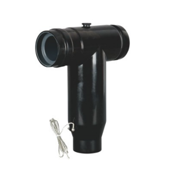
A T-Body Connector provides the main insulated connection between the medium-voltage cable and the RMU bushing.
Its role is not simply to carry current. The connector also has to maintain insulation around the energized interface, control the electrical field, provide an external screened surface, and connect mechanically to the equipment interface.
This is why a T-Body Connector should not be selected only from its nominal voltage rating.
For an OEM, switchgear manufacturer, distributor, or project contractor, an RMU drawing and cable datasheet are usually much more useful than a general request such as “we need a 24kV Separable Connector.”
Those documents show what the connector actually has to match.
Rear connectors when another interface is required
Some RMU arrangements require more than one connection at the same position.
In a compatible connector system, a rear connector can sometimes be installed behind the primary connector to create another insulated interface. This may be used for an additional cable, a surge arrester, or another part of the circuit arrangement.
The important point is that the rear connector is not simply an optional extension added afterward.
Its compatibility with the front connector, equipment interface, and available cable compartment depth should be considered from the beginning.
This becomes particularly important in compact RMUs because every additional connector increases the overall installation depth.
The Bushing Is Part of the Connection, Not Just Part of the RMU
It is easy to focus on the cable connector and treat the equipment bushing as a fixed detail.
In practice, the two parts should always be considered together.
The RMU bushing determines the physical interface that the Separable Connector must fit. Its geometry and electrical rating therefore directly influence the connector selection.
This becomes especially important during replacement or retrofit projects.
An existing connector model can be a useful starting point, but it should not be the only reference. The cable may have been changed, a replacement RMU may use a different interface, or the previous accessory may no longer represent the current installation.
In these situations, photographs of the existing connector and bushing can be useful, but they are most valuable when they are supported by the actual cable and equipment data.
Double-pass interfaces for branching requirements
Some medium-voltage distribution arrangements need an additional insulated connection point without changing the entire equipment connection.
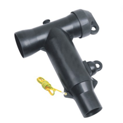
This is where double-pass bushing connector arrangements can be useful.
YIEOU’s medium-voltage accessory range includes double-pass bushing connectors for applications such as RMUs, compact substations, cable branch systems, and similar distribution equipment.
A double-pass arrangement can provide another connection path for a cable branch, compatible accessory, or protection component.
It should still be selected because the circuit requires that additional interface, rather than being treated as a standard component for every RMU project.
Busbar Connections Can Extend the RMU Accessory System
Not every RMU accessory is located at the cable entry.
In multi-circuit RMUs and compact switchgear systems, insulated connection components may also be used to connect several functional units together.
YIEOU’s product range includes a 35kV top-mounted busbar system designed around fully screened separable connector technology for multi-circuit RMU and compact substation applications.
This is useful because it shows that the accessory system can extend beyond a simple cable-to-bushing connection.
In this type of installation, compatible front and rear connectors may form part of an insulated busbar path between adjacent circuits.
The design then needs to consider more than the connector model itself. The number of circuits, spacing between units, current rating, connector orientation, and available installation space all influence the final arrangement.
For this reason, drawings are especially valuable when discussing multi-circuit RMU projects.
A connection that is electrically suitable still needs to fit into the actual equipment layout.
Cold-Shrink Accessories Complete the Cable Route Outside the RMU
The cable does not end at the RMU.
The other end of the feeder may connect to a transformer, another switchgear panel, an outdoor termination point, or another section of underground cable.
This means an RMU project can involve both Separable Connectors and more conventional cable accessories.
Cold-shrink terminations
A cable may enter the RMU through a Separable Connector while the opposite end uses a cold-shrink termination.
These products are not alternatives to each other. They simply solve different connection requirements along the same cable route.
The Separable Connector is designed around a defined equipment interface, while the termination prepares the cable for connection to another type of equipment or exposed terminal arrangement.
Cable joints
A cable joint becomes relevant when two cable sections need to be connected along the route.
This may happen because of cable length, network extension, cable replacement, or project installation conditions.
The distinction is straightforward.
A Separable Connector usually connects a cable to equipment.
A cable joint connects one cable section to another.
An RMU distribution project may need both, which is why the entire cable route should be considered before the accessory list is finalized.
Surge Protection Should Be Planned with the Connection Arrangement
Medium-voltage cable accessories do more than establish the main current path.
In some projects, the same insulated connection system also needs to accommodate surge protection.
Connector-type surge arresters can be used at suitable locations to help protect equipment against transient overvoltage from lightning or switching events.
Where the connector system allows it, a surge arrester may be integrated through an additional compatible interface rather than through a separate exposed connection.
This is one reason that rear connectors and double-pass arrangements can become important in certain RMU designs.
However, surge arresters should not simply be added because the interface is available. Their location and rating should follow the protection design of the actual network.
Grounding Also Depends on the RMU Design
Grounding arrangements vary between RMU designs and operating procedures.
Many RMUs already include dedicated switching and earthing functions, while some cable accessory systems can also provide additional grounding points for maintenance or testing.
The accessory arrangement therefore needs to be coordinated with the RMU itself.
For maintenance teams, the important issue is not simply whether a grounding accessory exists, but whether the complete system allows the cable circuit to be isolated and grounded according to the intended operating procedure.
This is another reason to consider the RMU, cable, and accessories as one coordinated system.
What Information Helps Us Select RMU Cable Accessories?
When we receive an RMU cable accessory inquiry at YIEOU, accurate project information is usually more useful than a long product description.
RMU and bushing information
The RMU model and rated voltage provide the basic equipment context, but the bushing interface is one of the most important details.
If an equipment drawing is available, it can help confirm the interface position, cable entry direction, compartment dimensions, and number of circuits.
For replacement projects, a clear image of the existing bushing and connector markings can also help identify the current arrangement.
Cable information
The next step is to confirm the actual cable.
Conductor material and cross-section, insulation type and diameter, screen construction, and overall cable dimensions all influence accessory selection.
This is why two cables with the same nominal voltage do not necessarily use exactly the same connector configuration.
For retrofit projects, it is particularly important not to assume that an old connector part number automatically matches the new cable.
Circuit arrangement
A simple single-line diagram often explains more than several pages of product descriptions.
It immediately shows where the incoming and outgoing cables are located, whether the RMU feeds a transformer, whether another cable needs to share the interface, and whether surge protection or other additional connections are required.
From this, the accessory package can be selected around the actual circuit instead of being assembled one component at a time.
Installation space
RMUs are intentionally compact, so mechanical space cannot be treated as an afterthought.
Cable bending radius, connector depth, cable entry direction, grounding leads, and access for installers all need to fit within the cable compartment.
This becomes especially important when a rear connector, surge arrester, or another additional component is installed behind the primary connector.
A connection can be electrically compatible and still be difficult to install if the completed assembly has not been checked against the available space.
A More Complete Approach to RMU Cable Accessories from YIEOU
When the RMU interface, cable data, circuit arrangement, and available installation space are considered together, it becomes clear that accessory selection is rarely about choosing one connector in isolation.
The main cable connection may use a T-Body Connector, while another interface may require a rear connector or double-pass arrangement. In a multi-circuit RMU, insulated busbar connections may also be involved. Beyond the RMU itself, the same feeder may continue through a cold-shrink termination or cable joint, while surge protection and grounding may need to be coordinated with the overall connection design.
This is why we usually look at the complete RMU cable connection before recommending individual products.
Not every installation needs all of these accessories. The correct combination depends on the equipment interface, cable construction, electrical ratings, circuit arrangement, and available installation space.
At YIEOU, we manufacture medium-voltage cable accessories and related connection products for RMUs, switchgear, compact substations, cable branch systems, transformers, and distribution networks.
For switchgear manufacturers, distributors, EPC contractors, and project procurement teams, we can work from equipment drawings, cable information, and connection requirements to help match the relevant accessories as a coordinated system rather than treating each product independently.

FAQ
What cable accessories are normally used with an RMU?
A typical RMU connection may use a Separable Connector such as a T-Body Connector together with the matching equipment bushing and cable adapter. Depending on the circuit, the project may also involve rear connectors, surge arresters, grounding accessories, busbar connection components, cable terminations, or cable joints.
The exact combination depends on the RMU design and cable system.
Is a T-Body Connector the same as a complete RMU cable connection?
No.
The T-Body Connector is the main visible connector body, but the complete connection also depends on the cable adapter, conductor connection, equipment bushing, and other compatible components.
Can a Separable Connector be selected only by voltage and current rating?
No.
Voltage and current ratings are important, but the equipment interface and cable dimensions must also be confirmed.
A 24kV or 35kV rating alone does not show whether a connector will fit a particular RMU.
When is a rear connector needed on an RMU?
A rear connector may be used when the system needs another compatible interface behind the primary connector, for example for an additional cable or surge protection arrangement.
Whether it is suitable depends on the connector system and the available installation space.
Can cold-shrink cable accessories be used in the same project as Separable Connectors?
Yes.
They often serve different parts of the same cable circuit. A Separable Connector may connect the cable to the RMU, while a cold-shrink termination or cable joint is used elsewhere along the cable route.
Can the same cable accessory configuration be used for every RMU?
No.
Even RMUs with the same nominal voltage and current rating may use different bushing interfaces, cable entry arrangements, compartment dimensions, and circuit configurations.
The cable itself can also change the required connector adapter, conductor connection, and installation dimensions.
For this reason, RMU cable accessories should be matched to the actual equipment and cable system rather than copied directly from another project with similar electrical ratings.