
During a cable extension, the spare space behind an existing T-shaped separable connector can look like an obvious place for a second cable. The difficulty appears when the new cable arrives: its connection point sits farther from the equipment, the bend crosses the original cable, or an arrester already occupies the rear position. A separable connector arrangement needs room for the complete assembly, including the parts that will be removed during maintenance. Getting the front and rear components in the right order is the first step. Checking what both cables do to the existing connection is just as important.
Réponse rapide
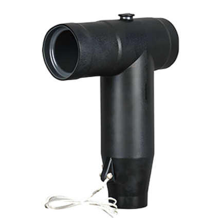
A second cable can connect through a compatible rear separable connector when the front connector, coupling parts, equipment bushing and enclosure support that arrangement. Our QJT 12/24-630A European Style Front Connector connects to the equipment interface. The matching HJT 12/24-630A European Style Rear Connector extends the cable connection behind it. The HJT cannot connect directly to a bushing socket or wall bushing.
The extra cable does not create a second switch or double the current rating of the equipment connection. Both cable terminations need their own cable matching, and the shared parts need a current assessment for the intended circuit. At YIEOU, we manufacture medium-voltage cable accessories and help match the front connector, rear connector and finishing components to the equipment drawing and actual cable data.
The Front Connector Establishes the Equipment Connection
The front and rear names describe where the components work. The front separable connector forms the connection between the cable and the equipment bushing. The rear connector attaches behind that front component to add another cable connection. Their similar T-shaped outlines do not make them substitutes for each other.
Two connectors may both carry a 630A rating and look almost identical, yet still be unable to fit the same equipment. The difference lies where the connector meets the bushing: the electrical contacts and insulating surfaces need to fit together correctly. When we match a connection for an RMU or transformer, that meeting point tells us more than the connector’s overall shape. A European C-type bushing, for example, calls for a connector designed around that interface; the current rating alone cannot establish a match.
For this European Connecteur séparable arrangement, identifying the installed front connector comes before ordering the rear part. A label, an assembly drawing and the equipment bushing designation provide a useful starting point. A front view of a black rubber body rarely identifies the complete coupling arrangement.
An existing 600A American-style connection needs a separate product review. Its current rating is close to 630A, but that does not establish a compatible rear interface. The same applies to a 200A loadbreak system. Moving between these families changes the connection system, not just the number printed on the accessory.
The Rear Connector Adds a Cable to the Same Connection
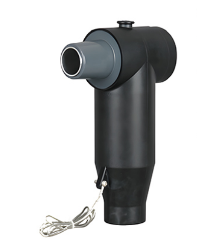
The HJT rear separable connector provides an extended cable connection through a compatible European front connector or another compatible rear connector. Its equipment-facing end is designed for that extension arrangement. It is not an alternative front connector for mounting directly on the equipment bushing.
Consider a cable branch box with one cable already connected through a front body. If the project calls for another cable at that same electrical connection, a rear separable connector may provide the additional termination. The original cable remains at the front position, while the new cable enters the rear body farther into the compartment.
This separable connector arrangement shares an electrical connection. It does not provide independent switching or protection between the two cables. If the new branch needs its own switching function, adding a rear body alone cannot provide it. That requirement belongs in the circuit arrangement before the cable accessories are finalized.
There is also a difference between a new branch and a second cable intended to operate in parallel with the first. Both involve two cable ends, but they serve different purposes. The equipment drawing and circuit diagram need to show which arrangement is intended so we can match the physical assembly to the correct connection duty.
The rear separable connector is therefore useful when the connection plan already calls for a shared point and the equipment permits the extension. Counting unused positions on the outside of a body does not answer those questions.
More Cable Connections Do Not Increase the Bushing Rating
Adding a second cable through a separable connector can change the current in the parts that both cables share. The front connector and equipment bushing may carry the combined current of two outgoing cables, depending on how the circuit is supplied. A rear connector does not provide a separate path around those shared components.
Our QJT product specification gives a continuous rated current of 630A. Installing two cable terminations behind one equipment connection does not turn that bushing connection into a 1260A supply point. Its permitted duty remains tied to the ratings and conditions of the complete assembly.
For a simple illustration, suppose one equipment connection supplies two outgoing circuits drawing 180A and 220A at the same time. The shared supply path carries 400A. Those example loads help identify the current path; they do not approve a particular installation. Cable capacity, equipment limits, operating temperature and fault duty still affect the final choice.
If two cables are intended to share one load in parallel, equal current sharing cannot be assumed from equal conductor area alone. The circuit designer needs to establish the cable arrangement and operating duty. Our role is to match the separable connector components to those requirements, including the current in each cable termination and the common connection.
Keep voltage requirements with this review. An extension must preserve the equipment’s required voltage and insulation level throughout the front body, rear body and closure. A larger cable or a higher-rated individual accessory does not automatically upgrade the existing assembly.
Match Each Cable to Its Own Connector Components
A front and rear pair can connect two cables with different dimensions, provided the selected configuration supports both. The cable entering the front separable connector and the cable entering the rear body each need a matching conductor contact and insulation interface. They do not have to use identical ordering details simply because they share an equipment connection.
For example, an existing copper cable and a new aluminium cable may have the same nominal conductor area. Their contact requirements can still differ. A change in cable manufacturer or insulation construction can also change the diameter over insulation, even when the conductor area remains unchanged.
That diameter is measured across the cable insulation at the part that fits the accessory. It is different from the overall diameter across the outer sheath. Using the sheath diameter to choose a separable connector cable interface can lead to the wrong selection.
Our QJT and HJT configuration information separates conductor area from insulation diameter. For project matching, we use both rather than treating the area as a complete cable description. The selected voltage version, conductor material and cable construction also need to match the intended kit.
When an older cable datasheet is missing, start with the available cable markings and equipment records. We can help identify what further information is useful. Measurements on prepared cable belong to the planned installation work under the applicable procedure; they are not a reason to disturb an operating connection just to obtain a quotation.
A separable connector extension is easier to specify when the two cables are described separately as front cable and rear cable. That simple distinction prevents the new cable details from accidentally replacing the original cable details in the order.
Check Depth and Cable Bends Together
The rear body moves the new cable termination farther away from the equipment mounting plane. That added depth affects more than door clearance. It changes where the new cable bends, where it needs support and how an installer reaches the closing components.
A useful side-view drawing shows the equipment mounting plane, the front connector, the rear connector and the final closure. It also shows the cable route down to the first support or entry point. This makes it possible to see whether the two cables approach their bodies naturally or have to cross immediately below them.
The outside dimensions of a separable connector body are only part of the space requirement. The cable has its own minimum bending radius, and assembly tools need access to the specified fastening positions. Space may also be needed to withdraw or separate a component during maintenance. A closed-door measurement checks only the final installed position.
Table 1. Space changes when a rear cable is added
| Position to review | What changes | Practical effect on the connection |
|---|---|---|
| Rear closure | The assembly projects farther into the enclosure | Check the door and the space needed to remove the closing part |
| New cable entry | The termination is farther from the equipment face | Check the bend and support position for the actual cable |
| Existing cable route | A second cable may cross the original route | Keep both cables aligned without pulling the bodies sideways |
| Adjacent phases | More components occupy the same compartment | Check the complete three-phase layout and access to fasteners |
| Earthing leads | Additional leads need a route to the specified earth point | Keep leads clear of closing surfaces and service access |
A large rear cable can be the limiting item even when the connector bodies fit. For instance, the available entry hole may place it directly beneath the front cable. Moving the cable sideways at the last moment can impose an awkward bend or side load. Resolving the entry and support position on the drawing is more useful than choosing a smaller-looking body from another interface family.
Each separable connector needs a cable approach that allows correct seating without using the bushing as a cable support. The support arrangement carries the cable load and preserves alignment after the assembly is complete.
Leave the Rear End Properly Closed
The last separable connector position still needs a defined finishing arrangement. Our HJT rear connector can be completed with a matching insulating plug or extended with another compatible rear connector or rear-connected arrester. These are different final configurations, each with its own parts and space requirements.
An insulating plug finishes the specified rear interface. A protective shipping cover serves a different purpose and cannot be assumed to provide the insulation required in service. The closing parts must match the voltage version and connector system, including the specified insulation and sealing components.
For a separable connector extension, the order should identify what occupies the final rear position. Otherwise, the main bodies can arrive while a necessary plug or coupling component is missing. A description such as “front and rear set” is less clear than a configuration drawing that shows the complete connection.
Connecteur identification also matters when spare parts are stored for later work. A spare part may look familiar while belonging to a different voltage version or mating arrangement. Keeping the exact component references with the equipment record helps the maintenance team identify the correct replacement.
The ability to connect another rear body does not establish an unlimited extension length. The permitted arrangement depends on the selected components, the equipment and available space. We review the proposed sequence as a complete separable connector assembly before recommending the parts.
Include the Arrester in the Space Review
A rear-connected surge arrester can occupy the same area needed for the additional cable arrangement. If the original connection already has an arrester behind the front body, the second cable cannot simply take that position without reviewing how the arrester will connect afterward.
Our HBLQ-17/50 European Style Rear-Connected Lightning Arrester is designed to work with matching European front connectors. The HJT application also allows a compatible rear-connected arrester at its tail. The intended combination needs confirmation as an assembly, including the coupling parts and the final installed position.
The arrester has a different job from the cable-carrying separable connector. Its zinc oxide elements provide overvoltage protection, and its earth connection forms part of that protection arrangement. Selecting it involves the network voltage, earthing conditions and protection requirements, in addition to the mechanical fit.
For example, placing the arrester behind the new rear cable body may increase the projection toward the door. Its earth lead also needs a suitable route. Moving it into a remaining gap can make inspection or replacement difficult, even when the gap appears large enough for the body itself.
Review the complete side view with the arrester included. If space is insufficient, the equipment arrangement needs another look. Omitting a required arrester or moving it to an unconfirmed position is not a connector selection solution.
Plan the Extension Around the Existing Assembly
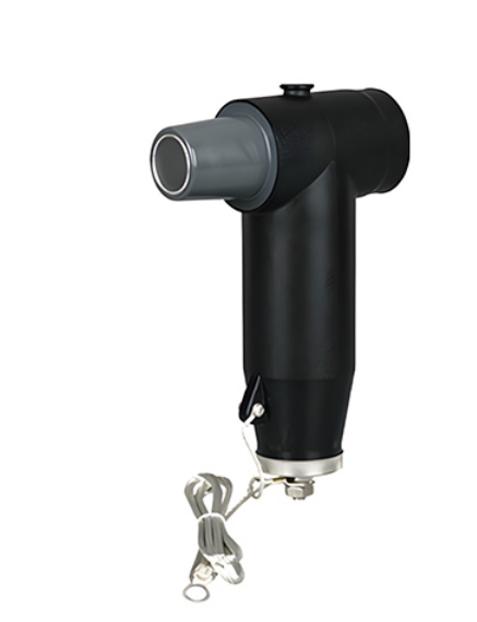
Adding a rear separable connector to an existing installation involves the condition of the retained parts as well as their model numbers. The front separable connector’s mating surfaces, coupling components and identification need review under the planned outage procedure. Compatibility with a new rear body does not establish that an old component is fit for reuse.
These European front and rear cable connections are not load switches. Separation and extension work take place with the circuit in the required isolated condition, following the installation’s voltage verification and earthing procedures. A loadbreak elbow’s operating capability cannot be transferred to a 630A front and rear arrangement.
A practical extension review compares the existing assembly drawing with the proposed completed assembly. It identifies the parts retained, the parts replaced and the new cable termination. The installation instructions for that exact combination determine fastening, cable preparation and assembly details; values from an unrelated kit are not a substitute.
For equipment manufacturers and project contractors, a drawing of one phase is a useful starting point, but the full three-phase arrangement still needs space review. The centre phase can have less working access than the outside phases. Cable supports and earthing routes can also differ across the compartment.
Send us the available bushing information, front connector reference, both cable descriptions and a side view of the enclosure. Our team at YIEOU provides technical support to match our Connecteur séparable components to the extension. If some details are missing, we can begin with the existing drawing or product markings and work through the remaining fit questions together.
FAQ
Can an HJT rear connector fit directly on the equipment bushing?
No. The HJT rear separable connector connects to a compatible European front connector or another compatible rear connector. The equipment-facing position requires the appropriate front connector and matching bushing interface.
Does adding a rear connector double the available current?
No. The shared front connector and equipment bushing retain their applicable ratings. The current assessment must include the load passing through the common parts of the connection.
Can the front and rear cables have different conductor sizes?
Yes, where the approved configuration supports the two selected cables. Each separable connector needs the correct conductor contact and insulation fit for its own cable, including conductor material and actual insulation diameter.
A compatible arrangement can include both, but the complete sequence and coupling parts need confirmation. Include the arrester body, earth lead and maintenance access when checking enclosure depth.
Is there enough space if the door closes?
Door clearance is only one check. A separable connector extension also needs cable bending room, support positions, fastening access and space for the planned removal of components.
What is the most useful information for an extension enquiry?
Start with the existing front connector reference, equipment bushing information and details of both cables. A side-view drawing or clear compartment photographs help us identify the layout questions and match the complete assembly.