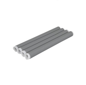
I. Product Overview
The 0.6-1kV cold shrink joint is a cold-shrink accessory specifically designed for intermediate connections of 0.6/1kV low-voltage power cables. Made of silicone rubber, it relies on its own elastic shrinkage to achieve insulation, sealing and protection of the cable intermediate joint. No heating tools are required, and installation is convenient. It is widely used in intermediate connection scenarios of low-voltage power cables to ensure the safe and stable operation of cable joints.
II. Product Characteristics
1. Insulation and sealing performance
- Made of high-quality silicone rubber, it has excellent insulation properties and can effectively withstand the working voltage of 0.6-1kV low-voltage systems. It has high insulation resistance and strong breakdown voltage resistance, ensuring the insulation safety of cable joints.
- After cold shrinking and retraction, it can fit tightly with the cable body and conductor connecting tube to form a continuous and reliable sealing structure, preventing moisture, dust and oil from entering the cable joint. It has excellent moisture-proof, waterproof and anti-fouling performance and IP68 protection.
- Silicone rubber material has good elasticity and sealing properties, which can adapt to the thermal expansion and contraction of cables, avoid gaps between joints and cables, and eliminate the risk of seal failure during long-term use.
2. Installation and Construction Characteristics
- The cold-shrink design eliminates the need for open flames or heating tools. Installation is achieved through the elastic retraction of the pre-expanded diameter, making the installation process safe and convenient, with no fire hazards, and suitable for special construction scenarios such as explosion-proof and fire-prohibited environments.
- Pre-expanded diameter forming allows for easy shrinkage during installation simply by pulling out the support core wire, resulting in fast construction speed, significantly shortening joint fabrication time and reducing construction costs.
- After installation, the connector has a neat and aesthetically pleasing appearance, without the uneven shrinkage, bubbling, or deformation issues common in heat-shrink products. It exhibits good consistency and facilitates subsequent maintenance and inspection.
3. Environmental and Weather Resistance
- With excellent weather resistance, it can adapt to a wide temperature range of -40℃ to +90℃. The elasticity and insulation properties of silicone rubber do not decrease under high and low temperatures, and there is no risk of cracking, embrittlement or deformation. It is suitable for various scenarios such as indoor, outdoor and underground applications.
- It is anti-aging, anti-ultraviolet, and resistant to ozone corrosion. It can be exposed to outdoor and buried environments for a long time, with a service life of more than 20 years. It requires no maintenance and reduces the cost of operation and maintenance.
- It is resistant to chemical corrosion and can adapt to harsh environments such as humidity, dust, salt spray, and mild acid and alkali. It has no risk of corrosion or degradation and is suitable for industrial and mining enterprises, coastal areas and other scenarios.
4. Mechanical and Adaptation Characteristics
- Silicone rubber materials have high mechanical strength, are tear-resistant and tensile-resistant, and can withstand mechanical stress during construction and operation without the risk of breakage or cracking. They are suitable for cable laying and tensile and bending conditions during operation.
- It is compatible with 0.6-1kV low-voltage power cables and can be used with single-core and multi-core cables (such as 4-core and 5-core). It has strong versatility and covers common low-voltage cable specifications.
- The connector has a compact structure and small size, making it suitable for installation in narrow spaces, cable trenches, cable wells, and other installation scenarios, with no installation space limitations.
III. Technical Parameters
| Parameter categories | project | Technical indicators |
| Electrical parameters | Applicable system voltage | 0.6/1kV AC |
| Rated voltage | 1kV | |
| Power frequency withstand voltage (5min) | 3.5kV, non-breakdown | |
| Insulation resistance | ≥1000MΩ | |
| Partial discharge quantity | ≤5pC (at 1.5 times rated voltage) | |
| Structural and material parameters | Main material | silicone rubber |
| Applicable cable core count | Single-core / 2-core / 3-core / 4-core / 5-core | |
| Applicable cable cross-section | 10mm²~400mm² (select according to specifications) | |
| Protection level | IP68 | |
| Structural form | Cold shrink joint (suitable for indoor/outdoor/underground use) | |
| Environmental parameters | Applicable altitude | ≤2000m (Customization available for high altitudes) |
| Ambient temperature | -40℃/ +90℃ (operating temperature), -40℃/ +70℃ (storage temperature) | |
| relative humidity | ≤100% (no condensation) | |
| Seismic resistance level | Level 8 | |
| Implementation Standards | GB/T 12706 “Extruded insulated power cables and accessories with rated voltage of 1kV (Um=1.2kV) to 35kV (Um=40.5kV)” and IEC 60840 “Test methods and requirements for extruded insulated power cables and accessories with rated voltage of 30kV (Um=36kV) and above to 150kV (Um=170kV)”. |
IV. Scope of Application
- Applicable voltage levels : 0.6/1kV low-voltage AC power cable systems.
- Applicable scenarios :
- Scenarios involving intermediate connections and extensions of low-voltage power cables;
- Cable joints for industrial and mining enterprises, commercial buildings, residential buildings, and low-voltage power distribution systems for new energy (photovoltaic/wind power);
- Low-voltage cable joints for special construction scenarios such as explosion-proof and fire-prohibited environments;
- Low-voltage cable joints in damp and dusty environments such as underground, cable trenches, and cable wells.
- Function and Purpose : To provide insulation, sealing and protection for intermediate connections of 0.6-1kV low voltage power cables, prevent moisture and dust from entering the cable joint, ensure the safe and stable operation of the cable joint, and avoid leakage, short circuit and fault tripping accidents caused by joint insulation failure and poor sealing.
V. Usage Conditions
1. Normal operating conditions
- Altitude: ≤2000m;
- Ambient temperature: -40℃ to +90℃; cable operating temperature shall not exceed the conductor’s long-term allowable operating temperature.
- Relative humidity: ≤100% (no condensation);
- Environmental conditions: No corrosive gases, no flammable or explosive media, no severe vibration or impact;
- Installation method: cold shrink installation. Simply pull out the support core wire to complete the shrinkage. The installation space must meet the bending radius requirements of the cable joint.
2. Special usage conditions (customization required)
- The altitude exceeds 2000m;
- The ambient temperature exceeds the range of -40℃ to +90℃;
- Severely polluted, salt spray, and chemically corrosive environments;
- High vibration and high impact conditions;
- Scenarios requiring non-standard cable cross-sections and special protection levels.
VI. Installation and Maintenance
1. Installation Requirements
- Before installation, check the product appearance. The silicone rubber joint should be free of cracks, damage, and bubbles, and the support core wire should be intact and free of deformation.
- Cut the cable according to the cable joint manufacturing process. The cutting length must meet the joint specifications. Avoid damaging the cable insulation layer during the cutting process. After cutting, clean the cable surface to remove oil, dust, and semi-conductive layer residue, and ensure that the surface is dry and clean.
- After crimping the cable conductor connecting tube, grind off the burrs at the crimped area and clean the surface of the connecting tube. Slide the cold shrink connector onto one side of the cable, adjust its position, and then pull out the support core wire to make the connector shrink evenly, covering the conductor connecting tube and the cable insulation layers on both sides, ensuring that the connector fits tightly with the cable body.
- After installation, check whether the joint shrinkage is uniform, without bubbles, wrinkles, or damage, and whether the joint position is offset. Once confirmed to be correct, the installation is complete.
2. Maintenance Requirements
- Regularly inspect the appearance of the connectors. Silicone rubber connectors should be free of cracks, damage, discharge marks, and dirt accumulation. The connectors should fit tightly with the cables without looseness or gaps.
- Regularly test the insulation resistance of the joints to ensure that the performance meets the requirements and to promptly identify potential insulation problems.
- Clean the surface of the connector to remove dust and dirt, and keep the surface dry and clean to avoid corrosion from oil and chemicals.
- If any abnormalities such as cracks, damage, discharge, or excessive insulation resistance are found in the joint, the joint must be replaced in time, and operation with defects is strictly prohibited.
VII. Precautions
- The product must be installed, debugged, and maintained by professional electrical personnel with low-voltage cable joint manufacturing qualifications. Operation by non-professional personnel is strictly prohibited.
- The product must be used with 0.6-1kV low-voltage power cables of the corresponding cross-section and number of cores. It is strictly forbidden to use cables of different specifications, otherwise it will lead to insulation and sealing failure and cause safety accidents.
- The product must not be disassembled or modified without authorization, otherwise the warranty and safety guarantee will be lost. It is strictly forbidden to forcibly stretch or cut the joints to avoid damaging the silicone rubber material.
- During installation, the cable must be stripped and the conductor connection tube crimped according to the process requirements to avoid damaging the cable insulation layer. The support core wire must be pulled out slowly to avoid uneven shrinkage or misalignment of the joint.
- When storing, it should be placed in a dry, ventilated, and cool environment, avoiding direct sunlight, high temperature, humidity, and compression. It is strictly forbidden to contact with sharp objects that may damage the connectors. The supporting core wires must be kept intact to avoid deformation.
- During operation, the condition of the joints should be checked regularly to avoid external pressure or collisions, and to prevent joint damage and seal failure.
VIII. Model Description
| Model Identification | meaning |
| 0.6-1kV | Applicable system voltage levels: 0.6/1kV low-voltage power cables |
| Single-core/Multi-core | Compatible with cable core count markings: single core/2 core/3 core/4 core/5 core |
| XXmm² | Compatible with cable cross-section markings, such as 25mm², 50mm², 150mm², 400mm², etc. |
IX. Implementation Standards and Certification
- International Standard: IEC 60840 “Test methods and requirements for extruded insulated power cables and their accessories with rated voltages of 30kV (Um=36kV) and above up to 150kV (Um=170kV)”;
- National Standard: GB/T 12706 “Extruded Insulated Power Cables and Accessories with Rated Voltages from 1kV (Um=1.2kV) to 35kV (Um=40.5kV)”;
- The product has passed the type test of the National Wire and Cable Quality Supervision and Inspection Center and meets the national power industry standards.
X. After-sales service
- Product warranty period: 18 months from the date of manufacture, or 12 months from the date of commissioning (whichever comes first).
- During the warranty period, products will be repaired or replaced free of charge if quality issues arise.
- We provide technical support, installation guidance, and customized services (adaptation to special specifications and working conditions).
Document Description
The technical parameters in this manual are based on standard operating conditions. Special operating conditions need to be customized according to actual needs. The final specifications shall be subject to the product technical agreement and type test report.
Appendix: Product outline diagram