Product Overview
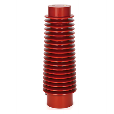
The 35kV-130×320 High-Voltage Sensor, corresponding to the model CG5-35Q/130×320, is an epoxy resin cast capacitive sensor designed for 35 kV indoor high-voltage electrical systems.
The product integrates three core functions: voltage presence indication, electrical interlocking against incorrect operation, and post-insulator support. It is widely used in high-voltage switchgear, ring main units, and other complete electrical equipment and is a key component for ensuring the safe operation of power distribution systems.
Product Features
Excellent Insulation Performance
The sensor is manufactured from high-quality epoxy resin using an integrated vacuum-casting process. Its optimized shed structure increases the creepage distance and improves electric field distribution.
The product provides high dielectric strength, arc resistance, corona resistance, and a low partial discharge level of no more than 5 pC. It can withstand system overvoltage and helps reduce the risk of electrical flashover.
Integrated Structural Design
The capacitive voltage-sensing rod and post insulator are integrated into a single structure. The sensor can replace a conventional post insulator in compatible applications without requiring an additional insulating support.
This integrated design simplifies the internal switchgear structure, reduces installation space, and provides high mechanical strength with reliable resistance to vibration and impact.
Reliable Interlocking Protection
The sensor extracts a voltage signal from the high-voltage circuit and supplies it to the voltage presence indicator and electromagnetic interlocking system.
It can provide forced interlocking for switchgear operating handles, access doors, mesh doors, and earthing switches. As long as the high-voltage circuit remains energized, the interlocking function remains active, helping prevent accidents caused by incorrect operation.
The indication and interlocking circuits operate independently and do not interfere with each other.
Strong Environmental Adaptability
The epoxy resin material provides reliable resistance to ageing, heat and humidity, contamination, and electrical tracking.
Its hydrophobic insulating surface supports stable operation across a temperature range of -35°C to +40°C, making the sensor suitable for most indoor high-voltage distribution environments.
Maintenance-Free Design
The fully sealed cast structure contains no exposed live parts and provides reliable protection against moisture, dust, and condensation.
Under normal operating conditions, the sensor requires minimal routine maintenance and offers a long service life.
Technical Specifications
| Parameter | Specification |
|---|---|
| Rated Voltage | 35 kV |
| Maximum System Voltage | 40.5 kV |
| Rated Frequency | 50 Hz |
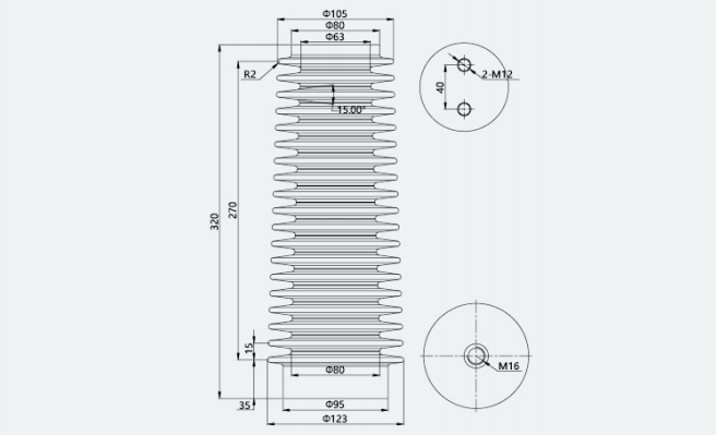
| Dimensions | 130 mm diameter × 320 mm overall height |
| Rated Insulation Level | 40.5/95/200 kV |
| Power-Frequency Withstand Voltage | 95 kV for 1 minute under dry conditions |
| Lightning Impulse Withstand Voltage | 200 kV peak, 1.2/50 μs |
| Partial Discharge | ≤5 pC at 1.1 Um/√3 |
| Creepage Distance | ≥1,050 mm, meeting the indoor pollution requirements of 35 kV systems |
| Capacitive Voltage Division Ratio | Customizable to match standard voltage presence indicators; typical value: 35 kV/100 V |
| Rated Bending Load | ≥8 kN |
| Tensile Load Performance | Withstands the rated tensile load for 1 minute without damage |
| Insulating Material | Epoxy resin |
| Applicable Standards | GB/T 25038-2010, DL/T 538-2006, IEC 60270 |
| Material Standard Reference | GB/T 20840.1-2010 |
Applications
Applicable Equipment
The sensor is suitable for indoor high-voltage electrical equipment with a rated voltage of 35 kV, a maximum system voltage of 40.5 kV, and a rated frequency of 50 Hz, including:
- 35 kV high-voltage switchgear, including KYN61-40.5
- Ring main units
- European-type and American-type box substations
- Disconnectors
- Earthing switches
- Circuit breakers
- Other indoor high-voltage distribution equipment requiring voltage indication and electrical interlocking
Main Functions
- Real-time indication of the energized status of high-voltage circuits
- Voltage signal transmission to a high-voltage presence indicator
- Forced interlocking of switchgear access doors and operating handles
- Prevention of incorrect operation while the circuit is energized
- Insulating and mechanical support for high-voltage conductors
- Capacitive voltage division and auxiliary power extraction
- Optional support for partial discharge monitoring applications
Operating Conditions
Environmental Conditions
- Ambient temperature: -25°C to +40°C
- Minimum temperature for special regions: -35°C
- Installation altitude: no more than 1,000 m
- For installations above 1,000 m, insulation correction must be carried out according to GB/T 11022
- Daily average relative humidity: no more than 95% RH
- Monthly average relative humidity: no more than 90% RH
- Daily average water vapour pressure: no more than 2.2 kPa
- Monthly average water vapour pressure: no more than 1.8 kPa
- The installation environment should be free from severe contamination, condensation, and excessive dust
Installation Conditions
- Installation location: indoor
- The environment must be free from flammable or explosive substances, corrosive gases, and severe vibration
- Installation orientation: vertical
- The high-voltage terminal must be connected to the high-voltage busbar or conductor
- The low-voltage terminal must be connected to the voltage presence indicator
- The grounding terminal at the bottom of the sensor must be reliably grounded
- Grounding resistance: ≤4 Ω
Prohibited Applications
The standard product must not be used in:
- Exposed outdoor environments
- Locations subject to strong ultraviolet radiation
- Environments with severe chemical corrosion or salt spray
- Locations containing flammable or explosive gases
- Installations above 1,000 m without insulation correction
- Power systems exceeding the specified voltage or frequency range
Installation and Maintenance
Installation Requirements
- Before installation, inspect the sensor for cracks, damage, bubbles, deformation, or other visible defects. The insulating surface must be clean and free from contamination.
- Install the sensor vertically inside the switchgear.
- Connect the high-voltage terminal securely to the busbar or high-voltage conductor.
- Connect the low-voltage terminal to the corresponding terminal of the voltage presence indicator.
- Connect the grounding terminal at the bottom of the sensor reliably to the switchgear grounding busbar.
- The cross-sectional area of the grounding conductor must be at least 6 mm².
- After installation, conduct an insulation withstand voltage test. The sensor may be put into operation only after the insulation performance has been confirmed as acceptable.
Maintenance Requirements
- Routine inspection: Check the sensor for surface damage, discharge marks, loose terminals, and abnormal temperature rise.
- Periodic testing: Conduct insulation resistance and power-frequency withstand voltage tests every one to two years.
- Cleaning: Clean the insulating surface using a dry, soft cloth. Do not use organic solvents that may damage the epoxy resin.
- Fault handling: If partial discharge, insulation breakdown, cracking, or other serious abnormalities are detected, immediately de-energize the equipment and replace the sensor. Repair while energized is strictly prohibited.
Packaging, Transportation, and Storage
Packaging
The product is packed in a moisture-resistant and shock-resistant carton with internal foam cushioning. A protective bag is placed over the product to prevent impact and moisture during transportation.
Transportation
- Avoid severe vibration, overturning, rain exposure, and mechanical impact.
- Do not transport the product together with corrosive substances.
- Handle the packaged product carefully and keep it upright where required.
Storage
- Store the product indoors in a dry and well-ventilated environment free from corrosive gases.
- Storage temperature: -10°C to +40°C
- Relative humidity: ≤85% RH
- Keep the product away from heat sources, ignition sources, and direct sunlight.
- Do not stack more than three layers.
Precautions
- This product is a high-voltage electrical component. Installation and maintenance must be carried out by qualified electrical personnel in strict accordance with high-voltage safety procedures.
- Do not remove, repair, or touch the sensor while the equipment is energized.
- The rated voltage of the sensor is 35 kV. Operation above the specified voltage level is prohibited.
- During installation, ensure that the safety clearances between the sensor, switchgear enclosure, and adjacent live components comply with GB 3906.
- The product has passed the required type and routine tests before delivery. Unauthorized disassembly or modification is prohibited.
Model Description
35kV-130×320
- 35 kV: Rated voltage level
- 130: Diameter of the sensor body in millimetres
- 320: Overall sensor height in millimetres
Corresponding standard model: CG5-35Q/130×320