
Bent Plate ABB 75 Wide Product Manual
Product Overview
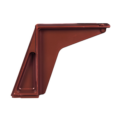
The Bending Plate ABB 75 Wide (Model: WB-40.5/ABB 75) is an epoxy resin insulating support component designed specifically for 35kV (40.5kV) high-voltage switchgear. Serving as a mating mounting fixture for contact boxes, it is primarily used to achieve reliable mechanical connection and insulating isolation between the contact box and the switchgear enclosure, ensuring safe and stable operation of high-voltage electrical systems.
Product Features
Excellent Insulation Performance: Formed by epoxy resin APG (Automatic Pressure Gelation) process. Insulation resistance ≥10¹⁴ Ω·cm; power-frequency dielectric breakdown voltage >35 kV/mm. Effectively blocks current leakage and prevents short circuits.
High Mechanical Strength: After curing, exhibits high tensile, compressive, and flexural strength, capable of withstanding long-term mechanical stress and vibration without deformation or cracking.
Good Thermal Stability: Continuous operating temperature range of -55°C to 155°C; short-term withstand temperature up to 180°C. No significant degradation of insulation performance at elevated temperatures.
Strong Corrosion Resistance: Resistant to attack by acids, alkalis, salts, and organic solvents. Suitable for industrial environments with heavy dust or high humidity. Long service life.
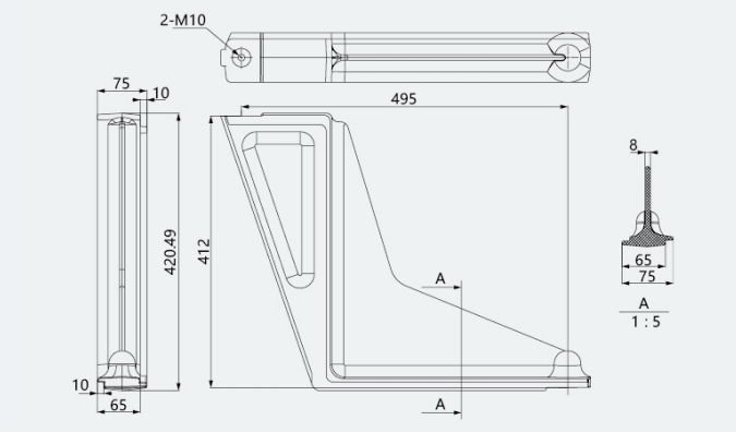
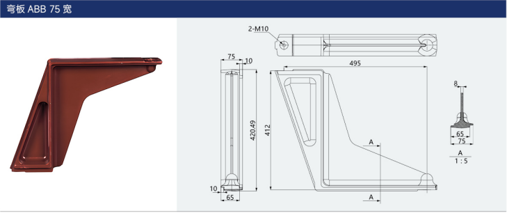
Optimized Structural Design: The 75 mm width specification is compatible with ABB-type contact boxes. The L-shaped structure provides stable support, with precisely positioned mounting holes for convenient field assembly and maintenance.
Flame Retardancy and Safety: Complies with UL 94 V-0 flame retardancy standard. Self-extinguishing after removal of ignition source; no toxic gas emissions. Enhances fire safety of the equipment.
Technical Parameters
Scope of Application
Primarily used as a mounting support component for contact boxes in KYN61-40.5, ZB-40.5, and similar 35kV metal-clad withdrawable high-voltage switchgear.
Suitable for high-voltage power transmission and distribution systems in power plants, substations, industrial and mining enterprise distribution rooms, for power reception, distribution, and protection.
Compatible with standard environments at altitudes ≤1,000 m; high-altitude variants support operation at altitudes ≤4,000 m.
Operating Conditions
(I) Normal Operating Environment
Ambient Temperature: -10°C to +40°C; daily average temperature not exceeding 35°C. Low-temperature custom variants support down to -25°C.
Altitude: ≤1,000 m (high-altitude variant: ≤4,000 m).
Relative Humidity: Daily average ≤95%; monthly average ≤90%.
Ambient Cleanliness: Free from heavy dust, smoke, corrosive/flammable gases, water vapor, and salt spray contamination.
Mechanical Conditions: No frequent severe vibration or shock; seismic intensity not exceeding Grade 8.
Installation Location: Indoor installation; avoid direct sunlight and rain exposure.
(II) Abnormal Operating Conditions
If operating conditions exceed the above environmental limits (e.g., high altitude, extreme temperatures, severely corrosive environments), the manufacturer must be consulted in advance to procure custom-specification products or implement additional protective measures.
Installation and Maintenance Notes
Inspect the product appearance before installation to ensure there are no cracks, chipping, voids, or other defects.
Use matched bolts to securely fasten the bent plate between the switchgear enclosure and the contact box. Apply tightening torque in accordance with the switchgear assembly requirements to avoid stress concentration.
After installation, verify insulation clearances to confirm compliance with GB 3906, IEC 298, and other applicable standards.
Periodic Inspection: Check the tightening condition of connecting bolts and the integrity of the surface insulation layer. Replace immediately if damage or creepage traces are observed.
Transport and Storage: Avoid impact and direct sun exposure. Store in a dry, well-ventilated environment at temperatures between 0°C and 35°C.
Applicable Standards
GB 3906-2020 — AC Metal-Enclosed Switchgear and Controlgear for Rated Voltages of 3.6 kV to 40.5 kV
IEC 62271-200:2019 — High-Voltage Switchgear and Controlgear, Part 200: AC Metal-Enclosed Switchgear and Controlgear for Rated Voltages above 1 kV and up to and including 52 kV
DL/T 404-2017 — AC Metal-Enclosed Switchgear and Controlgear for Rated Voltages of 3.6 kV to 40.5 kV
Enterprise Standard: Q/XXX 001-202X — Technical Specifications for Epoxy Resin Insulating Components
Product Images
| Parameter | Value |
|---|---|
| Product Model | WB-40.5 (ABB 75 Wide) |
| Rated Voltage | 35 kV (40.5 kV) |
| Material | Epoxy Resin (APG Process) |
| Width Specification | 75 mm |
| Applicable Frequency | 50/60 Hz |
| Power-Frequency Withstand Voltage (1 min) | 95 kV (phase-to-earth) |
| Lightning Impulse Withstand Voltage | 185 kV (phase-to-earth) |
| Insulation Resistance | ≥10¹⁴ Ω·cm |
| Flame Retardancy Rating | UL 94 V-0 |
| Surface Resistivity | ≥10¹² Ω |
| Volume Resistivity | ≥10¹⁴ Ω·cm |
| Compatible Contact Box Type | ABB-type 35 kV Contact Box |
| Mounting Method | Bolted between switchgear enclosure and contact box |
Product Information
General
Key source specifications include Rated Voltage: 35kV(40.5kV); Lightning Impulse Withstand Voltage: 185kV(phase-to-ground); Material: Epoxy Resin(APG Process Molded); Mounting Method: Securing Switchgear Contact Box.
Features
The epoxy resin casting process is employed to ensure stable insulation performance and high mechanical strength, while also facilitating maintenance operations.
High-altitude service requirements are included where the source file identifies a high-altitude version or customization.
Application
This 35kV insulation or sensing component is intended for switchgear, busbar, contact-box, bushing, sensor, or cabinet-support applications according to the matched model.
Product Images
Order information
Before ordering, confirm rated voltage, mounting method, and the required quantity according to the project drawings and source specification.