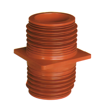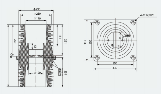
TG3-35Q/260×260×450 Wall-Through Bushing
Product Overview
The TG3-35Q/260×260×450 wall-through bushing is an epoxy resin insulating component specifically designed for 35kV high-voltage power systems. It is primarily used in power stations, substations, and high-voltage switchgear cabinets to allow conductive elements (busbars/copper bars) to pass through walls, partitions, or other grounded structures, while providing core functions of insulation support and electrical connection to ensure safe and stable operation of power systems.
Technical Parameters
| Parameter | Value |
|---|---|
| Rated Voltage | 40.5kV (compatible with 35kV systems) |
| Rated Frequency | 15–60Hz |
| Rated Current | 630A–3150A (customizable upon request) |
| Overall Dimensions | 260×260×450mm (mounting flange × total height) |
| Mounting Flange Dimensions | 260mm × 260mm |
| Material | Epoxy resin, APG process |
| Color | Red (natural epoxy resin color) |
| Power-Frequency Withstand Voltage (1 min) | 95kV (dry condition) |
| Lightning Impulse Withstand Voltage (peak) | 185kV |
| Partial Discharge Level | ≤5pC (at 1.1Um) |
| Creepage Distance | In accordance with GB/T 311 and relevant standards |
Product Features
Superior Insulation Performance
Formed using the epoxy resin monolithic APG (Automatic Pressure Gelation) process, the structure is dense and void-free, yielding high electrical insulation strength that effectively withstands the risk of dielectric breakdown at the 35kV level.
Shed-type outer insulation design increases creepage distance and enhances resistance to pollution flashover and moisture, suitable for outdoor and heavily polluted environments.
Reliable Mechanical Strength
The epoxy resin matrix offers excellent impact and flexural resistance, capable of withstanding electromagnetic force impulses during busbar short-circuit events, with no tendency toward deformation or cracking under long-term operation.
Square flange mounting structure provides uniform load distribution, ensuring secure connection to the cabinet or wall with outstanding seismic performance.
Optimized Electric Field Design
An internal shielding layer (optional) can be integrated to homogenize electric field distribution, suppress partial discharge, extend service life, and improve system operational stability.
Smooth inner and outer surfaces with no sharp edges eliminate electric field concentration and reduce the risk of corona discharge.
Strong Environmental Adaptability
Wide operating temperature range (−40°C to +120°C) with resistance to extreme temperatures and aging, enabling stable operation in outdoor, indoor, and high-altitude environments.
Flame-retardant and chemically resistant; unaffected by biological factors such as mold and insects, making it suitable for complex industrial environments.
Convenient Installation and Maintenance
Standardized flange dimensions and mounting hole patterns are directly compatible with mainstream 35kV high-voltage switchgear cabinets such as the KYN61-40.5.
Compact structure and lightweight design require no additional maintenance — only periodic cleaning of surface contamination is necessary.
Application Scope
Applicable to three-phase AC power systems with rated voltage of 10–35kV and frequency of 15–60Hz.
Primary application scenarios:
Internal busbar wall-through connections in high-voltage switchgear cabinets (e.g., KYN61-40.5 type).
Wall/partition busbar penetrations in substations and distribution rooms.
Insulation support and conductive connections in box-type substations, ring main units, and similar distribution equipment.
35kV high-voltage power distribution systems in industrial enterprises, mines, petrochemical plants, and related sectors.
Operating Conditions
(I) Normal Service Environment
Ambient temperature: −40°C to +120°C (short-term withstand up to 155°C).
Altitude: ≤3000m (derating or custom design required beyond this limit).
Relative humidity: daily average ≤95%, monthly average ≤90% (condensation-free conditions preferred).
Pollution level: Class IV or below (enhanced creepage distance models required for heavily polluted environments).
Locations free from severe vibration, shock, and flammable/explosive or strongly corrosive gases.
(II) Installation Requirements
Mounting orientation: vertical or horizontal installation is permissible; the flange face must be in full, flush contact with the wall or cabinet surface to ensure uniform load distribution.
Conductive connection: when threading copper bars/busbars through the interior, ensure uniform clearance between the conductor and the inner wall of the bushing to avoid localized stress concentration.
Sealing and protection: a sealing gasket must be installed between the flange and the mounting surface to prevent ingress of dust and moisture and to enhance insulation reliability.
Safety clearance: after installation, minimum electrical clearances between live parts and grounded parts must comply with GB/T 311 and other applicable standards.
Precautions
Transport and Storage: avoid impacts and drops; store in a dry, well-ventilated environment free from corrosive gases to prevent surface moisture absorption and contamination.
Pre-installation Inspection: verify that the product exterior is free from cracks and damage, that dimensions and mounting hole patterns match the installation site, and that electrical performance tests have been passed.
Operational Maintenance: periodically clean surface contamination from the bushing; inspect flange connecting bolts for loosening; if partial discharge or surface tracking marks are detected, shut down immediately for inspection and repair.
Type Selection: select the appropriate model specification based on the system rated current, voltage class, and installation space to avoid overloading or dimensional incompatibility.