CG3-10Q/95×125/140 (Tower Type) Indoor High-Voltage Presence Indicating Device Sensor
Product Overview
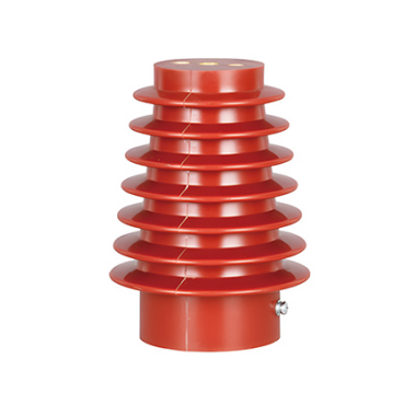
CG3-10Q /95×125/140 (Tower Type) Indoor High-Voltage Voltage Presence Indicating Device Sensor is a capacitive sensing element designed specifically for indoor high-voltage electrical systems. It employs an integrated molding process combining an SMC (Sheet Molding Compound) insulating housing with a high-voltage capacitor core rod. Used in conjunction with DXN-series voltage indicators and similar devices, it provides real-time indication of energized status in high-voltage circuits, enabling forced interlocking functions to prevent personnel from inadvertently entering live compartments. It serves as a critical safety component for 10kV and below indoor high-voltage switchgear.
Product Features
Superior Insulation Performance
The housing is fabricated from flame-retardant, aging-resistant, high-hydrophobicity SMC insulating material, offering high mechanical strength and strong resistance to pollution flashover. The multi-layer tower-type shed structure effectively increases creepage distance, ensuring insulation reliability in 10kV systems.
The internal capacitor core rod utilizes advanced surface-mount technology, providing stable capacitance values, high voltage-division accuracy, and zero drift during long-term operation.
Comprehensive Safety Protection
Compatible with live-line indicators and electromagnetic locks for interlocked forced lockout of disconnectors, earthing switches, and cabinet doors when the high-voltage circuit is energized, eliminating misoperation risk at the source.
No exposed live parts; fully insulated structural design prevents induced-voltage injury.
Structural and Manufacturing Advantages
One-piece tower-type molded construction with no splice joints, providing excellent moisture and condensation resistance, suitable for complex indoor operating environments.
Convenient installation with pre-drilled mounting bolt holes at the base, compatible with standard mounting dimensions of mainstream switchgear types including 10kV centrally-mounted cabinets, ring main units, and armored switchgear.
Strong Environmental Adaptability
Resistant to high and low temperatures, UV radiation, and aging; capable of continuous stable operation in environments from -25°C to +40°C, meeting the requirements of the vast majority of regions nationwide.
Compliant with GB/T 25081 “High-Voltage Live-Line Display Devices” and other relevant national standards; certified through type testing.
Technical Parameters
(See parameter table in Appendix)
Application Scope
Applicable Scenarios
10kV indoor high-voltage switchgear (centrally-mounted cabinets, ring main units, armored switchgear, box-type substations, etc.)
Indoor high-voltage distribution equipment, busbar compartments, cable compartments, and other high-voltage circuits
High-voltage electrical systems requiring live-line interlocking and misoperation prevention
Compatible Equipment
For use with DXN-T/Q, GSN, and other series of indoor high-voltage live-line indicators
Compatible with electromagnetic locks, disconnectors, and earthing switches to implement five-prevention interlocking functions
Operating Conditions
Environmental Conditions
Ambient temperature: -25°C to +40°C (extendable to -35°C to +45°C for special custom orders)
Altitude: ≤1000m (highland version customizable for altitudes of 1000m to 3000m)
Relative humidity: daily average ≤95% RH, monthly average ≤90% RH; water vapor pressure daily average ≤2.2kPa, monthly average ≤1.8kPa
Ambient pollution severity: Class II or below (no significant pollution, no corrosive gases)
Installation Conditions
Indoor installation only; avoid direct sunlight, rain exposure, and condensation
Installation location must be free from severe vibration and strong electromagnetic interference
Mounting surface must be vertical to ensure uniform load distribution on the sensor
Operating Conditions
System voltage fluctuation range: ±10% of rated voltage
Strictly prohibited for use under conditions exceeding rated voltage or rated frequency
Periodically inspect sensor appearance, wiring, and insulation performance to ensure no damage or loose connections
Installation and Maintenance
Installation Requirements
Inspect sensor appearance before installation; do not install if cracks, damage, or deformation are present
Secure the sensor in the designated position according to switchgear drawing requirements, ensuring base bolts are properly torqued
Connect the high-voltage terminal of the sensor reliably to the high-voltage busbar; connect the low-voltage terminal to the live-line indicator via conductor with secure, well-insulated connections
Perform insulation testing and dielectric withstand testing upon completion of installation; commission only after passing
Maintenance
Periodically clean the sensor surface; keep dry, free of dust accumulation and condensation
Inspect wiring terminals and mounting bolts every six months to ensure no loosening
Perform insulation resistance testing and power-frequency withstand voltage testing annually to verify insulation integrity
If physical damage or degraded insulation performance is detected, immediately take out of service and replace
Precautions
This product is a high-voltage electrical auxiliary component. Installation and maintenance must be performed exclusively by licensed qualified electricians in strict compliance with high-voltage safety operating procedures.
Strictly prohibited to disassemble or service the sensor while energized; avoid risk of electric shock.
The sensor must be used with its matched live-line indicator; do not substitute indicators of different model numbers, as this may compromise detection accuracy.
During transport and storage, avoid severe impact and compression to prevent damage to the insulating housing.
Product warranty period is 12 months from the date of manufacture; free repair or replacement service is provided for defects not caused by human damage under normal operating conditions.
Model Designation
CG3: Product series designation, representing SMC-insulated sensors for indoor high-voltage live-line display devices
10Q: Rated voltage 10kV; Q denotes indoor all-condition type
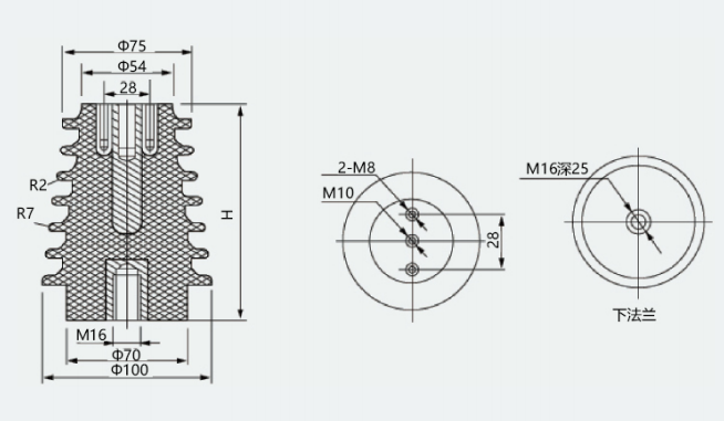
95×125/140: Structural dimensions — 95 denotes top diameter; 125/140 denotes two selectable heights
Tower Type: External structural form, multi-layer shed design
Appendix: Product Dimensional Diagram
| Parameter Category | Specification Details |
|---|---|
| Rated Voltage Class | 10kV (applicable to 3.6kV, 7.2kV, 12kV systems; compatible with indoor systems below 40.5kV) |
| Rated Frequency | 50Hz |
| Model | CG3-10Q/95×125/140 (Tower Type) |
| Structural Dimensions | Top diameter 95mm; height available in 125mm or 140mm; base mounting diameter compatible with standard switchgear types |
| Insulating Medium | Flame-retardant SMC composite material + high-voltage capacitor core rod |
| Creepage Distance | ≥230mm (12kV system) |
| Power-Frequency Withstand Voltage | 42kV/1min (12kV system) |
| Lightning Impulse Withstand Voltage | 75kV (peak value, 12kV system) |
| Capacitance Value | 100pF to 200pF (customizable to match specific live-line indicator) |
| Mechanical Strength | Flexural strength ≥4kN; excellent impact resistance |
| Flame Retardancy Rating | V-0 |
| Service Life | ≥20 years (under normal operating conditions) |