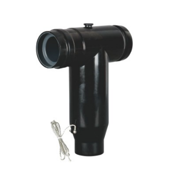
Shielded Cable Flexible Connector (also known as European-Style Elbow Flexible Cable Connector) is a specialized component used in medium-voltage power distribution systems to achieve flexible electrical connections between equipment. It is widely applied in 10kV/20kV/35kV European-style ring main units, compact substations, cable junction boxes, and similar installations.
Product Overview
The Shielded Flexible Cable Connector is a fully insulated, fully shielded, separable flexible connection component designed specifically for European-style power distribution equipment. It consists of European-style elbow connectors at both ends, a flexible cable in the middle section, and a continuous shielding structure. The assembly enables electrical interconnection between equipment while compensating for installation tolerances, thermal expansion and contraction, and minor vibration through its flexible structure. It serves as a replacement for conventional rigid copper busbar connections, enhancing the safety and reliability of power distribution systems.
Core Features
Electrical and Insulation Performance
Both ends feature European-style elbow connectors manufactured by integral injection molding of ethylene propylene diene monomer (EPDM) rubber, with built-in semi-conductive shielding layers that provide uniform electric field distribution, eliminate the risk of partial discharge, and are compatible with system voltage ratings of 10–35kV.
The intermediate flexible cable uses cross-linked polyethylene (XLPE) insulation, offering superior insulation performance and thermal resistance, capable of withstanding continuous operating current as well as short-circuit current impulses.
The fully shielded structure provides continuous grounding of the shielding layers across both connectors and the cable, eliminating external electric field interference and ensuring stable operation.
Flexibility and Installation Adaptability
The flexible cable is bendable, compensating for installation tolerances, thermal expansion and contraction, and minor vibration between equipment, thereby preventing deformation or damage caused by stress concentration.
Both ends adopt standard interfaces compatible with European-style ring main units, allowing direct plug-in connections without on-site welding or casting, resulting in high installation efficiency.
The modular design allows customization of cable length and phase color coding (e.g., red, green, and yellow for the three phases) based on equipment spacing, accommodating connection requirements across various applications.
Safety and Protection Features
The fully insulated, touchable structure ensures that the connector surface is at ground potential after installation, with no exposed live parts, eliminating the need for additional insulation protection and ensuring the safety of operation and maintenance personnel.
The fully sealed structure provides IP67 protection, effectively preventing the ingress of moisture, dust, and oil contaminants, making it suitable for humid, dusty, and other harsh environments.
Excellent weatherability allows operation across a wide temperature range of -40°C to +90°C with no degradation of insulation performance at extreme temperatures, providing a service life of more than 20 years.
Typical Application Scenarios
Ring Main Unit / Compact Substation Interconnection: Provides flexible electrical connections between European-style ring main units and compact substations, compensating for installation tolerances and thermal expansion and contraction.
Cable Junction Box Circuit Extension: Enables flexible connections among multiple circuits within cable junction boxes, replacing conventional rigid copper busbars and reducing the risk of short circuits and electric shock.
Power Distribution System Retrofit and Expansion: Used for flexible interconnection between equipment during renovation of aging distribution systems, eliminating the need for large-scale modification of equipment foundations.
Industrial, Mining, and Coastal Power Distribution: Suitable for equipment interconnection in humid, dusty, and salt-spray environments, offering strong weatherability and reliable operation.
Technical Parameters (Example: 10kV / 630A)
| Parameter Category | Item | Specification |
| Electrical Parameters | System Voltage Rating | 10kV AC (adaptable to 20kV/35kV) |
| | Rated Current | 630A (customizable to 1250A and other ratings) | |
| | Power Frequency Withstand Voltage (5 min) | 42kV, no breakdown | |
| | Lightning Impulse Withstand Voltage (peak) | 95kV, no breakdown | |
| | Partial Discharge Level | ≤5pC (at 1.5 times rated voltage) | |
| Structural and Material Parameters | Primary Material | Ethylene Propylene Diene Monomer (EPDM) + Cross-Linked Polyethylene (XLPE) Insulated Cable |
| | Ingress Protection Rating | IP67 | |
| | Interface Type | Standard European-Style Elbow Connector Interface | |
| Environmental Parameters | Applicable Altitude | ≤2000m (high-altitude versions available upon request) |
| | Ambient Temperature | -40°C to +90°C (operating); -40°C to +70°C (storage) | |
| | Relative Humidity | ≤100% (non-condensing) | |
| Applicable Standards | GB/T 12706, IEC 60840, GB/T 11022 |
Installation and Maintenance Guidelines
Installation Guidelines
Before installation, inspect the flexible connector for appearance defects: connectors must be free of cracks and damage; cables must be free of bulges and insulation damage; all accessories must be present.
Clean the equipment busbar interface to remove oil and dust, apply silicone grease evenly, and ensure smooth plug-in action and reliable contact.
Adjust the bending of the flexible connector according to the equipment spacing, avoiding excessive bending or twisting, and ensure the cable bending radius meets specified requirements.
After installation, verify grounding connections to ensure reliable grounding of both connector and cable shielding layers, achieving the “touchable” characteristic.
Maintenance Guidelines
Periodically inspect the flexible connector for appearance defects: connectors must be free of cracks, damage, and discharge marks; cables must show no signs of insulation aging, cracking, or deformation.
Periodically test the insulation resistance of the flexible connector to verify performance compliance and identify potential hazards in a timely manner.
Clean connector surfaces to remove accumulated dust and contaminants, preventing oil and chemical substances from corroding the rubber housing and cable insulation.
If abnormalities such as cracks, damage, discharge, or insulation resistance exceeding specified limits are detected, the flexible connector must be replaced immediately. Operation with known defects is strictly prohibited.
Applicable Standards and Certifications
International Standard: IEC 60840 — Test Methods and Requirements for Power Cables with Extruded Insulation and Their Accessories for Rated Voltages above 30kV (Um=36kV) up to 150kV (Um=170kV)
National Standards: GB/T 12706 — Power Cables with Extruded Insulation and Their Accessories for Rated Voltages from 1kV (Um=1.2kV) up to 35kV (Um=40.5kV); GB/T 11022 — Common Specifications for High-Voltage Switchgear and Controlgear Standards
The product has passed type testing by the National Wire and Cable Quality Supervision and Inspection Center and complies with national electric power industry standards.
Appendix: Product Outline Drawing