Product Overview
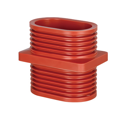
The TG3-10Q/110×180 Wall-Throught Bushing is an epoxy resin insulating bushing designed for medium-voltage distribution systems. Manufactured as a one-piece structure using the APG pressure gelation process, it is specially designed for indoor electrical assemblies rated at 10 kV and below.
The product is used where conductive busbars pass through switchgear partitions, walls, or grounded structures, providing electrical insulation, mechanical support, and secure busbar connection. It is widely used in KYN28 withdrawable switchgear, HXGN ring main units, and other complete electrical equipment.
Product Features
Material and Manufacturing Process
- Material: Manufactured from high-purity epoxy resin with high-quality curing agents and flame-retardant fillers, providing excellent electrical insulation, high mechanical strength, and strong ageing resistance.
- Manufacturing process: Formed through the APG pressure gelation process, resulting in a dense structure without internal bubbles or shrinkage cavities. The product offers high dimensional accuracy and good consistency. High-temperature curing and thermal ageing treatment ensure stable long-term performance.
- Structural design:
- A square mounting flange is positioned in the centre, while double corrugated shed structures are arranged at the upper and lower ends. This design increases the creepage distance, improves electric field distribution, reduces the risk of surface flashover, and enhances resistance to pollution and condensation.
- The 110 × 180 mm oval inner opening is suitable for corresponding copper busbars and conductive bars and supports both single- and double-busbar installation.
Electrical Performance
- High dielectric strength enables the bushing to withstand the long-term operating voltage of a 10 kV system, as well as lightning impulse and power-frequency overvoltage.
- The partial discharge level is extremely low at no more than 5 pC. Low corona discharge helps reduce insulation ageing during long-term operation and improves equipment safety.
- Excellent flame-retardant performance meets the fire-safety requirements of high-voltage electrical equipment.
Mechanical and Environmental Performance
- High mechanical strength allows the product to withstand busbar installation stress and thermal expansion and contraction during operation without cracking or deformation.
- Resistant to moisture, pollution, high temperatures, and low temperatures, making it suitable for demanding indoor environments.
- No special maintenance is required. Periodic cleaning of the insulating surface is normally sufficient.
- The product provides a long service life and stable operation under standard environmental conditions.
Technical Specifications
Main Electrical Parameters
| Parameter | Specification |
|---|---|
| Rated Voltage (Ur) | 10 kV, suitable for 10–35 kV systems |
| Rated Frequency (fn) | 50/60 Hz, suitable for 15–60 Hz systems |
| Power-Frequency Withstand Voltage | 42 kV for 1 minute, RMS |
| Lightning Impulse Withstand Voltage | 75 kV peak, 1.2/50 μs |
| Partial Discharge | ≤5 pC |
| Creepage Distance | ≥200 mm, meeting the insulation requirements of 10 kV systems |
| Applicable Standard | GB 4109-88, General Technical Requirements for Bushings for AC Voltages Above 1,000 V |
Structural Dimensions
| Parameter | Specification |
|---|---|
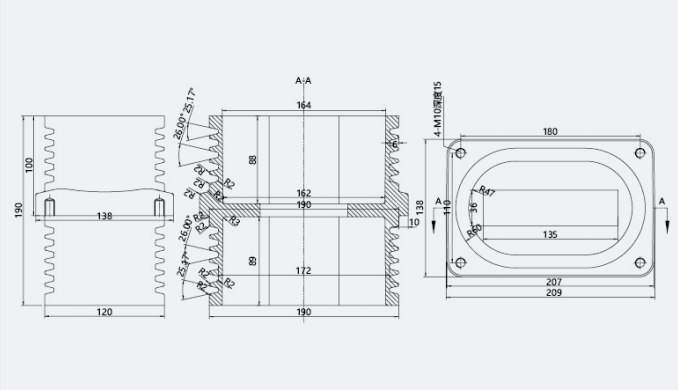
| Inner Opening Dimensions | 110 × 180 mm, oval |
| Overall Flange Dimensions | Approximately 140 × 210 mm |
| Overall Height | 190 mm |
| Flange Thickness | Standard design suitable for switchgear partition installation |
| Mounting Holes | Suitable for standard switchgear openings; customizable |
Applications
Applicable Equipment and Systems
- Three-phase AC systems rated at 10 kV and below with a frequency of 50/60 Hz.
- Power distribution equipment in power stations and substations.
- Indoor complete switchgear, including:
- KYN28-12 withdrawable switchgear
- HXGN-12 ring main units
- XGN fixed-type switchgear
- Insulation and support where busbars pass through switchgear partitions, equipment enclosures, or walls.
- Insulation and fixing of live conductors passing through grounded structures in transformers and other high-voltage electrical equipment.
Unsuitable Applications
- Unprotected outdoor installations exposed directly to sunlight and rain.
- Environments with severe salt spray or corrosive substances unless special protection is provided.
- Locations containing highly flammable or explosive substances, strongly corrosive gases, or conductive dust without additional protection.
- Systems operating above the specified rated voltage or frequency.
Operating Conditions
Environmental Conditions
- Ambient temperature: -40°C to +40°C.
- Daily average temperature: no more than +35°C.
- Relative humidity: no more than 85% at +20°C.
- Condensation is not permitted.
- Installation altitude: no more than 1,000 m. Insulation correction is required according to applicable standards above 1,000 m.
- The installation environment should be free from gases, vapours, chemical deposits, dust, dirt, and other explosive or corrosive substances that may seriously affect insulation performance.
- Severe vibration and mechanical impact should be avoided.
Installation Conditions
- The bushing may be installed vertically or horizontally on switchgear partitions or walls.
- The flange must fit closely against the mounting surface and be securely fastened and sealed with bolts.
- Before installation, confirm that the bushing surface is free from cracks, bubbles, mechanical damage, and other defects.
- When inserting a copper bar or busbar, maintain an even clearance between the conductor and the inner wall of the bushing.
- Avoid stress concentration and do not force the conductor through the opening.
- After installation, keep the surrounding area clean and free from foreign objects.
- Clean the insulating surface regularly to prevent pollution flashover.
Installation and Maintenance
Installation Procedure
- Check the dimensions of the switchgear mounting opening and confirm that they match the bushing flange. Remove any burrs from the opening.
- Insert the bushing through the mounting opening, ensure that the flange fits completely against the mounting surface, and align all mounting holes.
- Secure the flange using insulated bolts. Ensure reliable sealing and confirm that there is no looseness.
- Insert the copper bar or busbar and adjust its position so that it does not contact the inner wall or apply mechanical stress to the bushing.
- After installation, conduct an insulation test. The equipment may be put into operation only after confirming that no abnormalities are present.
Maintenance Requirements
- Routine inspection: Regularly inspect the bushing surface for cracks, discharge marks, contamination, and moisture.
- Periodic cleaning: Clean the bushing surface every 6 to 12 months using a dry, soft cloth. Do not use corrosive cleaning agents.
- Insulation testing: Conduct power-frequency withstand voltage and partial discharge tests once a year to confirm that the insulation performance remains acceptable.
- Abnormal conditions: If discharge marks, cracks, or damage are found, immediately de-energize the equipment and replace the bushing. Do not continue using a defective product.
Precautions
- This product is intended for indoor use only and must not be installed directly in an unprotected outdoor environment.
- Installation and maintenance must be carried out by qualified electrical personnel in strict accordance with high-voltage electrical safety procedures.
- Avoid impact and compression during transportation and storage to prevent cracking or damage.
- Store the product in a dry and ventilated environment. Protect it from moisture, high temperatures, and direct sunlight.
- Do not drill, cut, or otherwise machine the bushing, as this may damage the insulating structure.
- When the operating environment exceeds the conditions specified in this document, consult the manufacturer in advance for a customized design.
Model Description
TG3-10Q/110×180
- TG: Wall bushing
- 3: Product series
- 10Q: Rated voltage of 10 kV; Q indicates an indoor type
- 110×180: Inner opening dimensions, length × width in millimetres
Appendix
Common Problems and Corrective Actions
| Problem | Possible Cause | Corrective Action |
|---|---|---|
| Surface flashover | Surface contamination, condensation, or insufficient installation clearance | De-energize the equipment, clean the surface, reduce environmental humidity, and adjust the installation clearance |
| Bushing cracking | Excessive installation stress, sudden temperature changes, or mechanical impact | Replace the bushing immediately, improve the installation process, and avoid stress concentration |
| Excessive partial discharge | Internal bubbles, poor busbar connection, or insulation ageing | De-energize and inspect the equipment, and replace any unqualified bushing |
Packaging and Transportation
- The product is packed in a carton with foam cushioning to prevent impact damage during transportation.
- Handle the product carefully and avoid rolling, dropping, or placing heavy loads on it.
- After unpacking, inspect the product and confirm that there is no damage before installation.