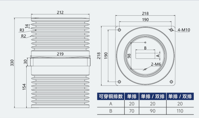
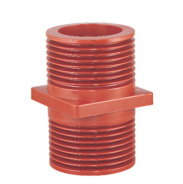
TG3-24kV(190×190×330) Bushing (with Shielding) specifically designed for 24kV medium-voltage power distribution systems. It is integrally molded using APG pressure gel technology and features an internal shielding layer. The product is mainly used for high-voltage conductive busbars/cables passing through switchgear partitions, walls, and other grounding components to achieve electrical insulation isolation, electric field homogenization, mechanical support , and busbar transition connection . It is widely used in 24kV medium-voltage switchgear, ring main units, and prefabricated substations, and is a core insulating component of medium-voltage power distribution systems.
II. Model Description
Model Identification
Meaning Explanation
TG3
Epoxy Resin Through-Wall Bushing Series (Special Type for Central Power Distribution Units)
24kV
Rated voltage level 24kV, suitable for three-phase AC systems of 24kV and below.
190×190×330
Key dimensional parameters: Inner diameter 190mm, flange mounting size compatible with 190mm standard hole position, total sleeve height 330mm.
With shielding
Built-in conductive shielding layer for uniform electric field and elimination of partial discharge
With a built-in fully shielded structure , it can uniformly distribute the electric field inside the bushing, completely eliminate the risk of partial discharge, significantly improve the insulation margin, and is suitable for long-term stable operation of 24kV systems.
It uses high-purity epoxy resin insulation material, which has high insulation strength and low dielectric loss, and can withstand severe electrical tests such as lightning strikes and power frequency withstand voltage.
The optimized umbrella skirt structure effectively increases the creepage distance, enhances anti-flashover and moisture-proof capabilities, and adapts to complex indoor environments such as humid and dusty conditions.
2. Reliable mechanical properties and reasonable structural design.
The epoxy resin one-piece molding process results in products with good density, no bubbles, no cracks, high mechanical strength, impact resistance, aging resistance, and the ability to withstand busbar installation stress and cabinet vibration.
The central square flange design ensures precise installation and positioning, excellent sealing performance, and effectively isolates the space inside and outside the cabinet, preventing air leakage and dirt accumulation between cabinets.
It has excellent explosion-proof performance, eliminating the risk of explosion associated with traditional porcelain bushings and significantly improving the safety of equipment operation; it is also lightweight, reducing the installation load on the cabinet.
3. Strong adaptability to process and environment
The APG pressure gel process ensures high product consistency, stable insulation performance, and long service life.
It has a flame retardant rating of UL94 V-0, is resistant to high and low temperatures and chemical corrosion, and meets the long-term operation requirements of indoor power distribution systems.
The maintenance-free design requires only periodic cleaning of surface stains, significantly reducing operation and maintenance costs.
IV. Main Technical Parameters
Parameter categories
Indicator values
Rated voltage
24kV (applicable to 10~35kV three-phase AC systems)
Rated frequency
50/60Hz (15~60Hz compatible)
Rated current
Compatible with 630A~3150A busbars/cables (select according to inner hole size)
Power frequency withstand voltage
Dry test: 65kV/1min, wet test: 50kV/1min
Lightning impulse withstand voltage
125kV (peak value)
Partial discharge
≤5pC (at 1.5Um)
creepage distance
≥630mm (meets the insulation requirements of a 24kV system)
Inner hole size
190mm diameter (circular inner hole)
Total height
330mm
Flange dimensions
Compatible with standard mounting holes for 24kV medium-voltage switchgear (customizable).
24kV indoor metal-armored center-mounted switchgear (KYN28A-24 and other models), armored withdrawable switchgear;
Ring main unit, prefabricated substation, and busbar/cable wall isolation in substations;
Insulation supports for conductive parts passing through partitions and walls in power plant and substation power distribution equipment;
Medium-voltage power distribution systems for new energy (photovoltaic, wind power) booster stations and power distribution rooms for industrial and mining enterprises;
Medium-voltage complete sets of equipment with strict requirements for electric field uniformity and partial discharge.
2. Adaptor conductor
It is compatible with round busbars and cables with a diameter of up to 190mm, or rectangular busbars of corresponding specifications, to meet the needs of high current transmission.
VI. Usage Conditions
1. Normal operating conditions
Ambient temperature: -40℃ ~ +40℃, with daily average temperature not exceeding +35℃;
Altitude: Not exceeding 1000m (high-altitude type can be customized, suitable for 1000~4000m);
Ambient humidity: Daily average relative humidity ≤95%, monthly average relative humidity ≤90%;
Installation location: Indoors, free from severe pollution, corrosive gases, and flammable or explosive substances;
Earthquake intensity: not exceeding 8 degrees, with no severe vibrations or impacts.
2. Special usage conditions (customization required)
High-altitude, highly polluted, and salt spray environment;
Extreme high and low temperature environments;
Customization requirements such as special installation dimensions and special shielding structures.
VII. Installation and Maintenance
1. Installation Requirements
Before installation, inspect the appearance of the bushing. There should be no cracks, bubbles, or damage. The insulation surface should be clean and dry, and the grounding terminal of the shielding layer should be intact.
The conductor (busbar/cable) passes through the inner hole of the bushing, ensuring that the conductor does not contact or squeeze the inner wall of the bushing, and leaving sufficient insulation gap;
The built-in shielding layer of the bushing must be reliably grounded to ensure a uniform electric field; the shielding layer must not be suspended in the air.
The flange is tightly fitted to the cabinet partition and bolts are tightened evenly to avoid stress concentration that could cause the sleeve to crack.
After installation, insulation resistance, partial discharge, and withstand voltage tests must be performed. The equipment can only be put into operation after its performance is confirmed to be qualified.
2. Maintenance Requirements
Routine inspection: Check the surface of the bushing for dirt accumulation, discharge marks, cracks, whether the flange seal is intact, and whether the grounding of the shielding layer is reliable;
Regular cleaning: Wipe surface stains with a dry, soft cloth or anhydrous alcohol. Do not use corrosive cleaning agents.
Preventive testing: Insulation resistance, withstand voltage, and partial discharge tests are conducted periodically according to electrical regulations to ensure performance compliance.
VIII. Precautions
It is prohibited to put the device into operation if the bushing is damaged, damp, severely contaminated, or the shielding layer is not grounded.
Avoid striking or bumping the sleeve during installation to prevent damage to the insulation structure and displacement of the shielding layer;
The sleeve is only suitable for indoor environments and is prohibited for outdoor use.
When selecting a model, the conductor size and cabinet mounting hole positions must be matched to avoid mismatch;
During transportation and storage, proper protection should be taken to avoid squeezing, moisture, high temperature exposure, and direct sunlight. The terminals of the shielding layer should also be protected.
IX. Customization and Services
We can customize non-standard products such as special sizes, special shielding structures, high-altitude types, and dirt-resistant types according to user needs;
We provide product technical support, installation guidance, and after-sales warranty services.