Product Overview
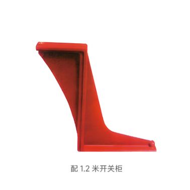
The WB-35Q/140 3AVS Insulating Bending Plate is an insulating support component specially designed for 35 kV high-voltage switchgear, particularly 1.2-metre switchgear configurations.
It is mainly installed in the busbar compartment and contact box area to provide electrical insulation and mechanical support, helping maintain the required electrical clearances and stable operation of the high-voltage circuit.
Manufactured through an integrated epoxy resin casting process, the product offers reliable electrical insulation and mechanical strength. It is one of the key insulating accessories used in 35 kV switchgear assemblies.
Technical Specifications
| Parameter | Specification |
|---|---|
| Model | WB-35Q/140 3AVS |
| Rated Voltage | 35 kV |
| Compatible Switchgear | 1.2-metre high-voltage switchgear, including KYN61 and similar 35 kV cabinet types |
| Material | Epoxy resin manufactured by APG casting |
| Colour | Red insulating protective colour |
| Electrical Clearance | Meets the safety clearance requirements of 35 kV systems, ≥300 mm |
| Insulation Resistance | ≥1,000 MΩ under normal room-temperature conditions |
| Power-Frequency Withstand Voltage | 95 kV for 1 minute, phase-to-earth |
| Lightning Impulse Withstand Voltage | 185 kV peak, phase-to-earth |
| Mechanical Strength | Designed to withstand the internal electrodynamic forces generated by switchgear short-circuit conditions |
| Flame-Retardant Rating | UL94 V-0 |
| Protection Level | Matches the switchgear enclosure, typically IP3X or IP4X |
Product Features
High Electrical Insulation Performance
The product is manufactured using an integrated epoxy resin casting process. Its smooth, uniform surface helps minimize bubbles, voids, and insulation defects.
The high dielectric strength effectively separates live conductors from grounded components, helping reduce the risk of electrical tracking, flashover, and short circuits.
Accurate Compatibility with 1.2-Metre Switchgear
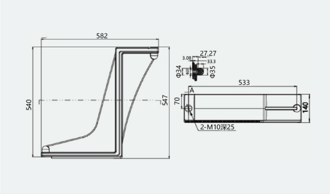
The structure and mounting positions are optimized for 1.2-metre 35 kV switchgear.
The preformed mounting holes correspond with compatible cabinet structures, allowing the product to be installed or replaced without additional drilling or machining.
Reliable Mechanical Stability
The L-shaped support structure provides good resistance to bending, impact, and deformation.
It can withstand short-circuit electrodynamic forces and the mechanical stresses generated during long-term switchgear operation, helping maintain the position and stability of busbars, contact boxes, and other internal components.
Resistance to Environmental Conditions
The epoxy resin material offers good resistance to high and low temperatures, moisture, ageing, and chemical corrosion.
It is suitable for indoor substations, industrial plants, transport power systems, and other demanding indoor electrical environments.
Improved Operational Safety
The red surface makes the insulating component easy to identify during installation, inspection, and maintenance.
Rounded edges help reduce the risk of accidental scratches and handling injuries while supporting compliance with electrical equipment safety requirements.
Long Service Life and Low Maintenance
The selected insulating material offers reliable resistance to ageing, cracking, and long-term electrical stress.
Under normal operating conditions, the product can provide a service life compatible with the switchgear assembly, with minimal routine maintenance requirements.
Applications
The WB-35Q/140 3AVS Insulating Bending Plate is suitable for:
- Busbar compartments of 35 kV indoor high-voltage switchgear
- Contact box areas in 35 kV switchgear
- KYN61-40.5 switchgear and similar 1.2-metre cabinet configurations
- Insulating support for busbars and other live conductors
- Electrical clearance compensation inside switchgear
- Mechanical fixing and positioning of contact boxes
- Electric field distribution optimization
- Compatible ABB-type and other mainstream 35 kV switchgear configurations
- Urban substations
- Industrial and mining power systems
- Rail transit power distribution systems
- Renewable energy power stations
- Other 35 kV power distribution applications
Operating Conditions
Environmental Conditions
| Condition | Requirement |
|---|---|
| Ambient Temperature | -40°C to +85°C |
| Short-Term Temperature Resistance | Up to +120°C |
| Relative Humidity | ≤95% at 25°C |
| Installation Altitude | ≤3,000 m |
| Installation Location | Indoor |
| Condensation | Not permitted |
| Corrosive Gases | Not permitted |
| Severe Vibration or Impact | Not permitted |
| Flammable or Explosive Media | Not permitted |
For installations above 3,000 metres, equipment derating, insulation coordination adjustment, or a customized product configuration may be required.
Electrical Conditions
| Parameter | Requirement |
|---|---|
| Rated System Voltage | 35 kV |
| Rated Frequency | 50 Hz |
| Short-Time Withstand Current | 25–40 kA, depending on the switchgear rating |
| Peak Withstand Current | 65–100 kA, depending on the switchgear rating |
The product must be used within the specified voltage and current parameters of the complete switchgear assembly.
Installation Requirements
Before installation, clean the mounting surface inside the switchgear. Remove oil, dust, moisture, metal particles, and other contaminants.
Install the product using suitable bolts and tighten them according to the switchgear assembly specifications.
The fastening force must be applied evenly. Excessive or uneven tightening may produce installation stress and cause cracking or deformation of the insulating component.
After installation, inspect the electrical clearance between the bending plate, live components, grounded parts, and the switchgear enclosure. Confirm that all clearances meet the applicable requirements for a 35 kV system.
The product must not be installed, removed, or adjusted while the equipment is energized. All work must be completed according to the required power isolation, grounding, and high-voltage safety procedures.
Inspection and Maintenance
The product requires minimal routine maintenance under normal operating conditions. However, its condition should be inspected during scheduled switchgear maintenance.
Inspection items include:
- Surface cracks
- Mechanical damage
- Electrical tracking marks
- Carbonization
- Arc erosion
- Surface contamination
- Moisture accumulation
- Loose mounting bolts
- Abnormal deformation
- Reduced electrical clearance
Clean the surface using a dry, soft, lint-free cloth. Do not use corrosive solvents, abrasive tools, or metal cleaning equipment.
Stop using the product and replace it immediately if cracks, severe ageing, tracking marks, carbonization, deformation, or other insulation defects are found.
Safety Precautions
- Avoid impact, compression, dropping, and improper stacking during transportation and storage.
- Do not strike, pry, bend, or force the product into position during installation.
- Do not drill additional holes, cut the structure, or modify the mounting dimensions.
- Keep the product away from sharp metal objects and corrosive chemicals.
- Do not install or remove the product while the equipment is energized.
- Installation and maintenance must be carried out by qualified electrical personnel.
- Replace the product immediately if surface cracking, tracking, carbonization, or other abnormal conditions are detected.
- Always use a replacement with the same model, dimensions, voltage rating, and insulation performance.
Selection and Ordering Information
| Item | Details |
|---|---|
| Product Model | WB-35Q/140 3AVS |
| Standard Compatibility | 1.2-metre 35 kV high-voltage switchgear |
| Typical Switchgear Type | KYN61-40.5 and compatible cabinet structures |
| Material | APG-cast epoxy resin |
| Customization | Customized versions are available for other switchgear dimensions, including 1.4-metre configurations |