
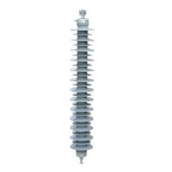
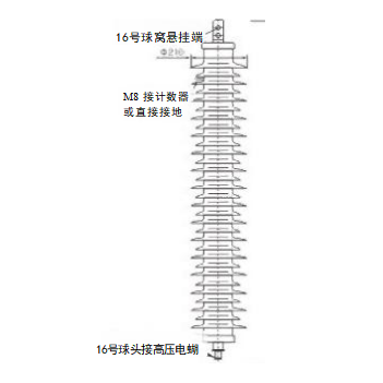
HY(YH)5W-3~6kV Series Surge Arresters
Product Overview
The HY(YH) series surge arresters are gapless metal oxide surge arresters designed specifically for 3~6kV AC systems. Covering three dedicated application scenarios — rotating machines, motor neutral points, and capacitors — these arresters feature a silicone rubber composite housing and provide superior overvoltage protection performance. They effectively limit lightning overvoltages and switching overvoltages, protecting the insulation of motors, capacitors, and other equipment from damage.
Product Characteristics
Electrical and Protection Performance
High-performance zinc oxide varistor discs are employed, providing excellent volt-ampere characteristics, low residual voltage, and high current withstand capacity, effectively limiting lightning overvoltages and switching overvoltages in the corresponding systems and protecting equipment insulation from damage.
Fast response speed enables instantaneous operation upon the occurrence of overvoltage, promptly dissipating overvoltage energy to prevent overvoltage from penetrating equipment. Protection performance is stable and reliable.
Excellent nonlinear volt-ampere characteristics result in extremely low leakage current and low power dissipation under normal operating voltage. Under overvoltage conditions, the arrester conducts rapidly and automatically restores to an insulating state after energy dissipation, requiring no maintenance.
Structural and Safety Features
An integral silicone rubber composite housing with no seams or air gaps provides excellent sealing performance, effectively preventing moisture and contamination from penetrating the interior and protecting the varistor discs from moisture damage.
An integrated modular structural design provides high mechanical strength, impact resistance, and vibration resistance, capable of withstanding mechanical stresses during transportation, installation, and operation without risk of deformation or damage.
Built-in upper and lower threaded terminals (M10/M12 selectable) allow convenient installation by direct series connection between the equipment and ground, requiring no additional auxiliary devices and compatible with various installation configurations.
The gapless design eliminates follow current during operation, removing the risk of explosion or fire caused by power frequency follow current, ensuring high operational safety.
Environmental and Weather Resistance
Excellent weatherability allows adaptation to a wide temperature range of -40°C to +90°C. The silicone rubber housing maintains its elasticity and insulating properties at both high and low temperatures without risk of cracking or embrittlement, suitable for both outdoor and indoor installations.
Moisture-proof, waterproof, pollution-resistant, and salt-spray-resistant, these arresters operate stably over the long term in harsh environments including humid, dusty, and salt-spray conditions. Strong hydrophobicity of the silicone rubber surface effectively prevents surface flashover.
Anti-aging, UV-resistant, and ozone-resistant properties support a service life of over 20 years with maintenance-free operation, reducing ongoing operation and maintenance costs.
Mechanical and Compatibility Features
High mechanical strength with impact and vibration resistance enables the arrester to withstand mechanical stresses from equipment operating vibrations and lightning current impulses without risk of deformation or damage. Seismic resistance rating reaches Grade 8.
Compatible with 3~6kV AC systems, with dedicated models designed for different applications including rotating machines, motor neutral points, and capacitors, offering broad versatility.
Compact size and lightweight construction allow convenient installation by direct mounting to equipment terminal boxes or distribution equipment without complex installation procedures.
Technical Parameters
Note: System nominal voltages marked with “*” are dedicated voltage classes for motors/capacitors.
| Application | Arrester Model | Arrester Rated Voltage (kV) | System Nominal Voltage (kV) | Continuous Operating Voltage (kV) | DC 1mA Reference Voltage (kV) | Maximum Residual Voltage (kV, peak) | 2000μs Square Wave Current Withstand (A) | 4/10μs High Current Withstand (kA) | Leakage Current at 0.75× DC Reference Voltage (μA) | Creepage Distance (mm) | Dimensions (mm) | Terminal Specification |
|---|---|---|---|---|---|---|---|---|---|---|---|---|
| Rotating Machine | HY(YH)2.5W-4/9.5 | 4 | 3.15* | 3.2 | ≥5.7 | Steep-front: 10.7, Lightning: 9.5, Switching: 7.6 | 200 | 65 | ≤50 | 115 | Φ102×167 | M10 |
| Rotating Machine | HY(YH)2.5W-8/18.7 | 8 | 6.3* | 6.3 | ≥11.2 | Steep-front: 21.0, Lightning: 18.7, Switching: 15.0 | 200 | 65 | ≤50 | 225 | Φ198×190 | M10 |
| Motor Neutral Point | HY(YH)1.5W-2.4/6 | 2.4 | 3.15* | 1.9 | ≥3.4 | Lightning: 6.0, Switching: 5.0 | 200 | 65 | ≤50 | 75 | Φ105×224 | M12 |
| Motor Neutral Point | HY(YH)1.5W-4.8/12 | 4.8 | 6.3* | 3.8 | ≥6.8 | Lightning: 12.0, Switching: 10.50 | 400 | 65 | ≤50 | 155 | Φ105×224 | M12 |
| Capacitor | HY(YH)5WR-3.(5)/13.5 | 3.8(5) | 3* | 2(4) | ≥7.2 | Lightning: 13.5, Switching: 10.5 | 400 | 65 | ≤50 | 155 | Φ105×224 | M12 |
| Capacitor | HY(YH)5WR-7.6(10)/27.0 | 7.6(8) | 6* | 4(8) | ≥14.4 | Lightning: 27.0, Switching: 20.8 | 400 | 65 | ≤50 | 225 | Φ198×190 | M10 |
Application Scope
Applicable voltage class: 3~6kV AC low-voltage distribution systems, covering dedicated voltage classes for motors and capacitors.
Application scenarios:
Rotating machines: lightning and overvoltage protection for 3.15kV/6.3kV motors;
Motor neutral points: overvoltage protection for 3.15kV/6.3kV motor neutral points;
Capacitors: switching overvoltage and lightning overvoltage protection for 3kV/6kV capacitor banks;
Lightning protection for motor and capacitor equipment in industrial and mining enterprises and new energy (PV/wind power) distribution systems.
Function: Limiting lightning overvoltages and switching overvoltages, dissipating overvoltage energy to ground, protecting the insulation of motors, capacitors, and other equipment from damage, preventing overvoltage-induced equipment breakdown and burnout failures, and ensuring the safe and stable operation of the distribution system.
Operating Conditions
Normal Operating Conditions
Altitude: ≤2000m;
Ambient temperature: -40°C to +90°C, equipment operating temperature compliant with relevant standards;
Relative humidity: ≤100% (non-condensing);
Environmental conditions: free from corrosive gases, flammable/explosive media, and severe vibration and shock (compatible with motor operating vibration conditions);
Installation method: fixed installation via upper and lower threaded terminals, with the upper terminal connected to equipment/distribution lines and the lower terminal reliably grounded; installation space must satisfy insulation clearance requirements.
Special Operating Conditions (Requiring Customization)
Altitude exceeding 2000m;
Ambient temperature outside the -40°C to +90°C range;
Severely polluted, salt-spray, or chemically corrosive environments;
High-vibration or high-impact duty;
Non-standard voltage classes or special current withstand capacity requirements.
Installation and Maintenance
Installation Requirements
Before installation, inspect the product appearance to confirm the silicone rubber housing is free of cracks, damage, and air bubbles, and that the terminals are intact, free of corrosion and deformation.
Clean the terminal surfaces to remove oil, dust, and foreign matter, ensuring the terminals are dry and clean. Check the grounding resistance of the earthing device to ensure it meets requirements (≤4Ω for low-voltage systems).
Connect the upper terminal of the arrester to the equipment/distribution line and reliably ground the lower terminal. Tighten the terminals to the specified torque. After installation, the arrester shall be mounted vertically with no looseness or inclination.
After installation, perform an insulation resistance test and confirm the result is acceptable before placing the arrester into service.
Maintenance Requirements
Periodically inspect the product appearance to confirm the silicone rubber housing is free of cracks, damage, discharge marks, and accumulated contamination; terminal connections shall be firm and free of looseness; the grounding terminal connection shall be reliable and free of corrosion.
Periodically test insulation resistance and leakage current to ensure performance meets requirements and to identify potential faults in a timely manner.
Clean the product surface to remove accumulated dust and contamination, keeping the silicone rubber surface dry and clean, and avoiding corrosion by oil or chemical substances.
If the product exhibits any abnormalities such as cracks, damage, discharge, or out-of-specification insulation resistance, immediately take it out of service and replace it. Operation of a defective product is strictly prohibited.
Precautions
Installation, commissioning, and maintenance must be carried out by qualified electrical personnel holding credentials for medium- and low-voltage distribution work. Operation by non-qualified personnel is strictly prohibited.
The product must be used with equipment of the corresponding voltage class and application scenario. Mismatching of models is strictly prohibited, as this will result in protection failure and safety incidents.
The product must not be disassembled or modified without authorization, as this will void the warranty and safety assurance. Use of non-specified tools to forcibly install or remove terminals is strictly prohibited.
During installation, damage to the silicone rubber housing is strictly prohibited. Terminals must be tightened to the specified torque to prevent heating and discharge caused by poor contact.
For storage, place the product in a dry, ventilated, cool environment, away from direct sunlight, high temperatures, moisture, and compression. Contact with sharp objects that could damage the silicone rubber housing is strictly prohibited.
During operation, periodically check the grounding resistance of the earthing device to ensure reliable grounding, preventing protection failure due to inadequate grounding.
Model Designation
| Model Identifier | Description |
|---|---|
| HY(YH) | Series designation for composite-housed metal oxide surge arresters |
| 1.5/2.5/5 | Nominal discharge current class (1.5kA/2.5kA/5kA) |
| W | Gapless structure designation |
| R | Capacitor application designation |
| 3~6kV | Applicable system voltage class, covering dedicated scenarios from 3kV to 6kV |
| 4/9.5, 8/18.7, etc. | Arrester rated voltage / lightning impulse residual voltage (peak) |
Standards and Certifications
International standard: IEC 60099-4, Metal oxide surge arresters without gaps for AC systems;
National standards: GB 11032, Metal oxide surge arresters without gaps for AC systems; DL/T 804, Application guide for metal oxide surge arresters in AC power systems; GB/T 11032, Metal oxide surge arresters without gaps for AC systems;
The product has passed type tests conducted by the National High-Voltage Apparatus Quality Supervision and Inspection Center and complies with national power industry standards.
After-Sales Service
Product warranty period: 18 months from the date of manufacture or 12 months from the date of commissioning, whichever comes first;
Free repair or replacement for product quality issues within the warranty period;
Technical support, installation guidance, and customization services (special specifications and special duty adaptation) are provided.
Document Note
The technical parameters in this manual are based on standard operating conditions. Special operating conditions require customization based on actual requirements. The product technical agreement and type test reports shall serve as the final reference.
(Note: Portions of this document may have been generated by AI.)