
An underground cable connection can look well protected: the conductor is enclosed, the bushing is covered, and the cable screen is connected to earth. Yet those features do not explain what happens when a surge reaches the equipment. A transient can arrive along the circuit even when the cable termination is clean and correctly assembled. The practical question is whether the connection also needs a surge arrester, and how that arrester fits the existing interface. For a Separable Connector assembly, insulation, surge limitation and earthing have related but different jobs. Understanding those jobs makes it easier to specify a complete connection without confusing a cable elbow with an elbow-shaped protection accessory.
Быстрый ответ
A Separable Connector carries current and maintains an insulated connection between the cable and equipment. A compatible surge arrester limits transient overvoltage by providing a controlled path to earth. The arrester adds a protection function; it does not increase the connector’s continuous current rating, replace its insulation, or act as a load switch.
The useful starting point is the actual equipment interface and the protection requirement at that location. At YIEOU, we manufacture medium-voltage cable accessories and match our Разъемный соединитель assemblies with suitable bushings, junctions and surge-protection accessories. An arrester that physically fits still needs the correct electrical characteristics, an appropriate earth connection and enough space for the complete installation.
Insulation and Surge Protection Solve Different Problems
The insulation in a Separable Connector separates the energized conductor from the grounded surroundings. Its shape and mating surfaces help control the electrical stress around the cable end and equipment interface. That insulation must withstand the conditions specified for the connection, but it does not actively hold every arriving voltage surge below a chosen value.
A surge arrester has a different role. It responds to an overvoltage and limits the voltage across its terminals while conducting surge current toward earth. The connector and arrester therefore work together: one forms the cable connection, while the other contributes to protecting the insulation of the connected system.
This distinction matters when reviewing a connection after storm-related damage. A thicker-looking rubber body or a higher current label does not demonstrate better surge protection. Similarly, fitting an arrester cannot correct damaged mating surfaces, a poorly prepared cable or an unsuitable conductor contact. Those conditions belong to the connection itself.
A Separable Connector installation may be appropriate with or without a local arrester, depending on the network protection arrangement. An underground route alone does not settle that decision. The cable may connect to an overhead section or other equipment through which transients can reach the cable circuit. The useful question is where protection is required and what insulation it is intended to protect.
We keep that distinction clear when discussing an accessory assembly. The Separable Connector specification establishes the interface and cable fit. The protection specification establishes the required arrester characteristics and location.
An Elbow Arrester Creates a Path to Earth
An elbow-shaped cable connector and an elbow surge arrester can look related because both use a compact insulated interface. Their internal electrical paths explain why they cannot be treated as interchangeable cable components.
The cable-side Separable Connector connects the cable conductor to the equipment. The arrester connects the energized point to earth through metal-oxide elements. Under normal conditions, those elements have high resistance and carry only a small leakage current. During a suitable transient, their resistance falls sharply, allowing surge current to flow while limiting the voltage. As the transient subsides, the arrester returns toward its normal high-resistance condition.
In a Separable Connector system, that makes the arrester a branch of the connection rather than an extra cable feeder. Its earth lead is part of its function. It is not a second outgoing phase conductor, and the arrester is not intended to carry the circuit’s normal load current to earth.
For example, where an American-style connection provides the matching 200A interface, our JY BLQ-17/50 elbow arrester can bring surge protection to that connection point. Its elbow form helps it fit the accessory arrangement, but the reason for including it is the metal-oxide protection path inside.
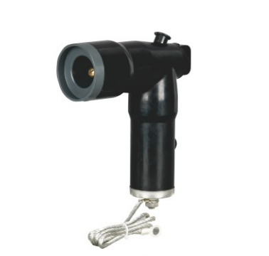
A grounding elbow performs another task: it provides an intentional grounding connection under the required maintenance conditions. An insulating cap closes an unused interface. Neither accessory has the same job as the arrester. Choosing among them starts with the required electrical function, even when their mating interfaces belong to the same product family.
Read the Arrester Ratings Separately from the Connector Rating
Several numbers can appear on the same assembly, and they describe different stresses. The continuous current of a Separable Connector describes its load-carrying duty. An arrester’s nominal discharge current describes an impulse duty. A figure expressed in kiloamperes on the arrester is therefore not a higher continuous-current rating for the cable connection.
Voltage labels need similar care. The network voltage, arrester rated voltage, continuous operating voltage and residual voltage have different meanings. Selecting by the largest printed number can produce the wrong conclusion in either direction.
For our JY BLQ-17/50, the specified arrester rated voltage is 17kV, the continuous operating voltage is 13.6kV, and the lightning impulse residual voltage is no more than 50kV at the specified 5kA discharge current. These values describe the arrester. They do not make the attached cable connector a 50kV connection, nor do they establish suitability for every network carrying a similar voltage label.
Table 1. What the connection and arrester ratings describe
| Rating or information | What it describes | Why it matters at the cable interface |
|---|---|---|
| Connector continuous current | Normal load-carrying duty | The existing cable path keeps its own current limit |
| Arrester continuous operating voltage | Voltage it can withstand continuously | It must suit the voltage appearing across the arrester in service |
| Arrester rated voltage | A rating associated with specified operating-duty tests | It is assessed with the other arrester characteristics |
| Residual voltage at a stated impulse current | Voltage across the arrester during that discharge condition | It contributes to the insulation-protection assessment |
| Temporary overvoltage capability | Permitted overvoltage magnitude and duration | Network earthing and fault-clearing conditions affect the requirement |
The network’s earthing arrangement can influence phase-to-earth voltage during a fault. That is why a familiar nominal system voltage is only the beginning of arrester selection. Continuous operating voltage, temporary overvoltage capability and protection level need to work together; simply choosing a higher voltage rating is not automatically the better result.
For a Separable Connector enquiry, we can start with the equipment and network information already available. The project protection requirements then help establish which arrester characteristics need confirmation. A complete study is not necessary to begin the conversation, but a matching interface alone cannot settle those electrical questions.
Match the Actual Interface Before Choosing the Arrester Shape
An arrester has to mate with the connection provided by the equipment or accessory assembly. The visible outline is only a clue. Contact geometry, insulating surfaces and the specified connection system determine whether the parts are compatible.
A 200A American-style interface, a 600A deadbreak interface and a 630A European-style interface are separate arrangements. The current numbers cannot be used as a ladder of interchangeable fittings. A Separable Connector from one arrangement does not accept the other arrangement’s arrester merely because both components are described as elbows or T-bodies.
There are purpose-made ways to provide a different accessory interface. Our JY ZHT-15kV 600/200 integral deadbreak bushing, for example, converts the specified 600A deadbreak interface to a 200A loadbreak interface and is intended to work with matching accessories, including an MOV elbow arrester. This is a defined component relationship, not permission to push a 200A accessory directly onto any 600A connection.
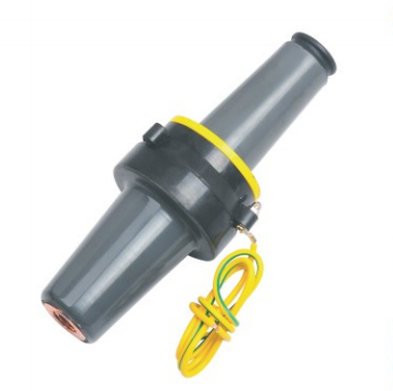
The resulting 200A Separable Connector interface also does not upgrade the original connection’s operating capability. The 600A deadbreak portion remains a deadbreak connection. Fitting an accessory with a loadbreak interface does not turn that portion into a device for interrupting load current.
European rear-connected arresters use another arrangement. Where an arrester connects behind a compatible front or rear body, its mating position and coupling parts differ from those of an American-style elbow accessory. The Separable Connector assembly drawing identifies the actual connection to be made. This is more useful than comparing photographs or assuming that similar current ratings imply common hardware.
An arrester is connected to an electrical point, but its location also has physical consequences. At a junction, several interfaces may share the same internal conductor. That can provide a convenient place for an arrester branch, provided the mating products and the protection arrangement suit the application.
Our JY MP-15kV 200A loadbreak junction provides multiple connection positions for compatible accessories. In a suitable Separable Connector arrangement, one position may serve a cable and another a surge-protection accessory. The junction in this Separable Connector assembly establishes the common connection; the arrester contributes its protective function at that location.
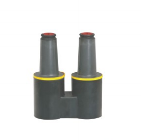
Using a port for an arrester means that port is occupied. It is no longer available for a future cable without changing the arrangement. The number of interfaces shown on a junction therefore does not equal the number of cable feeders that remain available after caps, arresters and other accessories have been allocated.
There is also a difference between sharing an electrical point and protecting every piece of equipment equally. The separation between the arrester and the equipment matters during a fast transient. A port that is convenient mechanically is not automatically the best protection location. The connection layout needs to reflect the point identified by the equipment’s protection requirements.
For a Separable Connector extension, this becomes particularly relevant when a new cable would occupy the existing arrester position. Moving the arrester farther along an assembly changes more than the photograph of the completed connection. Its leads, distance from the protected terminals and access for maintenance may all change. The revised Separable Connector arrangement needs to retain the intended protection as well as the additional cable.
The Earth Connection Is Part of the Protection
A grounded outer screen and an arrester earth lead may appear in the same compartment, but their functions deserve separate attention. The screen provides the intended grounded surface of the accessory. The arrester earth connection carries surge current as part of the protection path. Neither connection can be omitted because the other is present.
The path matters as well as the terminal. During a rapidly changing surge, a long or unnecessarily indirect lead can contribute additional voltage. This is why an arrester fitted close to the equipment can still need careful attention to its actual connections. Extra loops retained for convenience can work against the purpose of a compact installation.
The practical aim is a short, direct, properly secured route that follows the approved arrangement. That does not mean stretching a lead tightly across the compartment or altering the arrester. The supplied connection and the equipment’s earthing provision have to accommodate the installation without pulling on the accessory.
At a Separable Connector location, cable screens, earth conductors and the arrester lead also need room around the cable bends and supports. An earth lead trapped against a sharp edge or hidden behind a moving cable can complicate inspection and replacement. Разъем interfaces make the assembly detachable, but the earthing path must be restored correctly whenever the arrangement is changed. A secure mechanical fit at the phase interface does not prove that the surge-current path to earth is complete. Both belong in the finished connection review.
Check the Complete Assembly Inside the Compartment
The outline of a bare Separable Connector is only part of the space requirement once surge protection is added. An elbow arrester occupies a branch position; a rear-connected arrester adds depth. Coupling parts, earth leads, cable bends and the movement needed for removal all influence whether the arrangement is practical.
A useful side view starts at the equipment mounting plane and includes the complete accessory assembly. It shows whether a rear component approaches the door, whether an elbow branch enters another phase’s working space, and where the earth lead reaches the grounding provision. The drawing is most useful when it includes cable support positions rather than leaving the cables as straight lines.
The cable itself still needs its own match to the Separable Connector. Conductor size, conductor material and diameter over insulation determine the relevant cable-side components. Adding an arrester does not compensate for an unsuitable cable adapter or contact. Cable stiffness and bending requirements can also determine whether the chosen accessory position is usable.
Maintenance access deserves attention before the assembly is approved. A cabinet door that closes over the installed parts does not prove that the arrester can be removed with the required tools and movement. The connection may need additional space in service even when its final operating position is compact.
We use these details to match the connection as an installed assembly. For equipment manufacturers repeating the same arrangement across several panels, confirming one complete phase layout first helps reveal space conflicts before they are repeated. The final Separable Connector review still covers all phases, because entry positions and adjacent components can differ.
Keep Protection Matching Connected to the Project
The most useful request brings the existing Separable Connector arrangement and the intended protection point into the same discussion. An equipment bushing reference or drawing identifies the interface. Cable information identifies the cable-side fit. Network voltage, earthing conditions and the specified protection requirements guide the arrester assessment.
When only part of that information is available, a model reference and a clear description of the application are enough to begin discussing the arrangement with us. We can identify which product family is relevant and which details remain open. This avoids treating a catalogue name as a complete connection specification.
For a replacement, the old arrester label provides useful starting information, but it does not establish that the original selection still suits the network. Changes to equipment, connection position or earthing arrangements can affect the review. Likewise, a new arrester does not by itself establish that the retained Separable Connector and bushing are fit for continued use.
At YIEOU, we provide project support for matching our Разъемный соединитель assemblies to the equipment interface and application conditions. The aim is a connection that fits the equipment, retains the correct operating limits and places surge protection where the project requires it.
Часто задаваемые вопросы
Does a Separable Connector provide surge protection on its own?
Its insulation withstands specified electrical stresses, but it does not perform the voltage-limiting function of a surge arrester. Whether a local arrester is required depends on the equipment and network protection arrangement.
Is an elbow surge arrester the same as a loadbreak cable elbow?
No. A cable elbow connects the cable conductor to equipment, while an elbow arrester provides a metal-oxide path between the energized point and earth. Similar shapes or mating interfaces do not give them the same electrical function.
Does a 5kA arrester increase the connector current rating?
No. The 5kA value describes the arrester’s specified impulse discharge duty. The Separable Connector, bushing and cable retain their own continuous current limits.
Can a 200A arrester fit a 600A deadbreak connection?
A compatible transition component may provide the required 200A interface, as with the specified JY ZHT integral deadbreak bushing arrangement. That does not make all 200A and 600A parts interchangeable or change the deadbreak operating requirement.
Can an insulating cap replace an arrester on a spare port?
A cap closes and insulates the matching unused interface; it does not provide surge limitation. If the port is assigned to protection, replacing the arrester with a cap changes that function.
What information helps match an arrester to a Separable Connector?
The equipment interface, existing assembly, network voltage, earthing arrangement and protection requirements are the main starting points. A compartment drawing and cable details help us confirm how the selected accessories will fit together.