
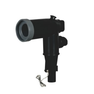
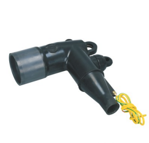
A Separable Connector provides a removable, insulated connection between a medium-voltage cable and equipment such as transformers, ring main units, switchgear, compact substations, and cable branch systems.
Its main advantages are clear: the connection can be insulated and shielded, equipment can be disconnected without permanently rebuilding the cable termination, and compatible accessories can support branching, grounding, testing, surge protection, and future system changes.
However, a Separable Connector also has important limitations. It must match the cable, voltage class, current rating, equipment interface, and intended operating method. A loadbreak connector and a deadbreak connector cannot be treated as the same type of connection, and similar-looking interfaces are not automatically interchangeable.
For this reason, the real value of a Separable Connector comes from using the correct connector as part of a correctly matched medium-voltage cable accessory system.
What Are the Main Advantages of Separable Connectors?
For many medium-voltage distribution systems, the biggest advantage is not simply that the connector can be removed. It is that the cable-to-equipment interface becomes more modular, insulated, and easier to manage.
| Advantage | What It Means for the Project |
|---|---|
| Insulated connection | Helps keep the energized interface enclosed when the system is correctly assembled |
| Separable structure | Cable and equipment can be disconnected according to the specified operating procedure |
| Compact arrangement | Suitable for transformers, RMUs, switchgear, and cable branch equipment |
| Flexible configuration | Supports radial feeds, loop feeds, branching, and different connection layouts |
| Accessory compatibility | Can work with suitable bushings, junctions, caps, grounding accessories, and surge arresters |
1. Insulated and Shielded Connections Support Compact Equipment Layouts
One important reason for using a Separable Connector is to avoid an exposed cable termination at the equipment interface.
In a properly designed system, the connector body provides insulation around the cable connection, while conductive or semiconductive shielding layers help control the electrical field and maintain the intended external shielding structure.
This is especially useful in compact equipment such as:
- ring main units;
- pad-mounted transformers;
- compact substations;
- medium-voltage switchgear;
- cable branch boxes;
- underground distribution systems.
The result is a cleaner and more enclosed connection arrangement compared with an exposed live-front termination.
However, this benefit depends on correct installation. The connector body, cable screen, grounding components, equipment interface, and related accessories must all be assembled according to the specified design.
A shielded connector should not be viewed as a single component that automatically makes every installation safe.
2. Equipment Can Be Disconnected Without Rebuilding the Entire Cable Termination
A conventional permanent termination may require more work when equipment needs to be replaced or rearranged.
A Separable Connector creates a removable interface between the cable and equipment.
When the correct operating and safety procedures are followed, the connector can be separated from the compatible equipment-side interface. This can make equipment replacement, cable isolation, system modification, and maintenance more practical.
For example, a transformer may need to be removed for maintenance while the existing underground cable remains in place. A properly configured separable connection can make this process more manageable than rebuilding the cable termination from the beginning.
This does not mean every separable connector can be disconnected under load.
The operating method still depends on whether the connection is loadbreak or deadbreak.
3. Separable Connectors Support Flexible Distribution Layouts
Medium-voltage cable networks are not always simple point-to-point connections.
A project may require:
- one incoming cable connected to one transformer;
- an incoming and outgoing cable forming a loop;
- multiple cable branches;
- a reserved connection for future expansion;
- temporary grounding during maintenance;
- surge protection at an equipment interface.
A Separable Connector system can support these arrangements through compatible bushings, junctions, T-body connectors, elbows, protective caps, grounding accessories, and other medium-voltage cable accessories.
For example, a simple radial-feed transformer may only require one cable connection.
A loop-feed arrangement may require a second connection so the cable route can continue toward another transformer or distribution point.
If several branches are required, a suitable junction system may be more appropriate.
This modularity is one of the strongest advantages of separable connector systems, but every additional interface should have a clear electrical purpose.
4. Compatible Accessories Can Make Maintenance and Expansion Easier
A Separable Connector rarely works alone.
Depending on the system design, a complete connection may include:
- elbow connectors;
- T-body connectors;
- bushing inserts;
- equipment bushings;
- junctions;
- insulating caps;
- grounding elbows;
- surge arresters;
- test-point accessories.
This gives engineers more flexibility when planning operation and maintenance.
An unused compatible interface, for example, can be insulated with an appropriate protective cap. A grounding accessory may be included where the maintenance procedure requires a grounding point. A surge arrester may be incorporated where the protection design calls for one.
The important point is that these components should be selected as a coordinated system.
A connector accessory should not be chosen only because it appears to fit physically.
5. Standardized Interfaces Can Simplify System Matching
Separable connector systems are commonly designed around defined interface requirements.
This can make equipment and cable accessory selection more systematic. Instead of designing a completely different termination for every transformer or switchgear unit, projects can use recognized interface families when the corresponding equipment and connector specifications match.
However, standardized does not mean universally interchangeable.
Two products may have:
- the same rated voltage;
- the same current label;
- similar dimensions;
- similar external appearance;
and still belong to different interface structures or require different mating components.
Before confirming a Separable Connector, we normally recommend checking the equipment-side interface together with the cable information.
This is more reliable than selecting by appearance or model name alone.
What Are the Main Limitations of Separable Connectors?
The limitations of a Separable Connector are mainly related to matching, operating conditions, installation, and system design.
These limitations do not mean separable connectors are unsuitable. They simply mean the connector has to be selected and installed as part of the complete medium-voltage connection system.
1. Interface Compatibility Must Be Confirmed Carefully
This is one of the most important limitations.
A Separable Connector only works correctly when it matches the intended equipment interface.
The project should confirm details such as:
- voltage class;
- rated current;
- loadbreak or deadbreak interface;
- equipment bushing type;
- connector interface structure;
- conductor size;
- cable insulation diameter;
- contact components;
- installation direction.
A physically similar connector should not be forced onto an incompatible interface.
Incorrect interface matching can affect contact position, mechanical fit, insulation coordination, sealing, and electric-field control.
This is why we prefer to check the connector, cable, and equipment interface together when supporting a project.
2. Cable Size Alone Is Not Enough for Connector Selection
A Separable Connector cannot normally be selected only from the conductor cross-section.
Cable construction varies.
Two cables with the same conductor size may have different:
- insulation thicknesses;
- insulation diameters;
- conductor constructions;
- screen structures;
- outer dimensions.
For connector installation, the actual cable dimensions can be critical.
The connector body and cable preparation must fit the specified insulation range. The conductor contact or lug also needs to match the conductor.
For this reason, providing the cable datasheet or actual cable dimensions can help us confirm a more accurate configuration.
This information makes it easier to avoid compatibility problems before the accessories arrive on site.
3. Not Every Separable Connector Can Be Operated Under Load
This is one of the most important technical boundaries.
Separable does not automatically mean loadbreak.
Loadbreak and deadbreak connectors serve different operating requirements.
Loadbreak Connectors
A loadbreak Separable Connector is specifically designed for defined switching operations when used with the correct mating interface, operating tools, ratings, and procedures.
A common example is a 200A-class loadbreak elbow system.
Even then, loadbreak capability should not be interpreted as permission to disconnect the connector casually while energized. The connector, mating interface, system conditions, operating procedure, and trained personnel all matter.
Deadbreak Connectors
A deadbreak connector is intended to be connected or disconnected only after the circuit has been properly de-energized according to the required safety procedure.
Higher-current systems commonly use deadbreak arrangements.
If the project requires a particular switching function, that requirement should therefore be identified before the connector is selected.
A deadbreak connector should never be treated as a loadbreak device simply because it is mechanically removable.
4. A Separable Connector Is Not a Substitute for Switchgear
The ability to separate a connector can sometimes create another misunderstanding.
A Separable Connector is part of the cable connection system. It should not automatically be treated as a replacement for the switching and protection functions provided by circuit breakers, load-break switches, disconnectors, or other switchgear.
The connector handles the cable-to-equipment interface.
The switchgear handles the switching, isolation, protection, and control functions defined by the electrical system design.
Some loadbreak connector systems provide specified loadbreak operating capability, but this does not turn every cable connector into a general-purpose switching device.
For installations requiring frequent operation, the switching philosophy of the entire system should be considered rather than relying only on the cable connector.
5. Installation Quality Has a Direct Effect on Performance
Separable connectors are manufactured components, but their final performance also depends on field installation.
Cable preparation needs to be controlled carefully.
Typical installation concerns include:
- incorrect stripping dimensions;
- damage to cable insulation;
- poor semiconductor screen removal;
- contamination of the insulation surface;
- incorrect contact installation;
- incomplete connector insertion;
- unsuitable lubricant use;
- improper grounding or screen connection.
Even a correctly selected connector can develop problems if the cable preparation or assembly is incorrect.
This is one reason clear installation instructions and correct tooling are important for medium-voltage cable accessories.
We also recommend confirming cable information before supply so that the components arriving on site already match the intended cable range and equipment interface.
6. Space and Cable Routing Still Need to Be Considered
Separable connectors can support compact equipment layouts, but they do not eliminate physical installation requirements.
Medium-voltage cables have minimum bending limitations, and the connector itself requires sufficient room for installation and future operation.
Before finalizing the arrangement, the project should consider:
- cable entry direction;
- bending space;
- connector orientation;
- front clearance;
- neighboring phases;
- available operating space;
- grounding accessory access;
- future maintenance access.
This becomes especially important in compact substations and RMUs where cable compartments are relatively small.
A connector may be electrically suitable but still be inconvenient for a particular cable direction or cabinet layout.
7. Voltage and Current Ratings Must Match the Actual System
A Separable Connector has defined electrical ratings.
It should not be selected simply because the connector looks similar to another product used in a different system.
The connector system needs to match the actual:
- system voltage;
- maximum operating voltage;
- continuous current requirement;
- insulation level;
- short-circuit requirements;
- equipment interface.
For example, a 200A connection system and a 600A connection system are designed for different current and interface requirements.
Likewise, connectors intended for different voltage classes should not be mixed simply because their external shapes appear similar.
Correct rating selection is therefore essential to maintaining a reliable cable-to-equipment connection.
Are the Advantages Greater Than the Limitations?
For applications that require insulated, removable medium-voltage cable connections, the advantages usually make separable connector systems highly practical.
Most of the limitations can be controlled through correct selection, matching, installation, and operating procedures.
The most important checks are:
- Confirm the system voltage and current.
- Identify whether loadbreak or deadbreak operation is required.
- Confirm the equipment-side interface.
- Check the cable conductor size and insulation diameter.
- Review cable routing and installation space.
- Select compatible bushings, junctions, caps, and grounding accessories.
- Follow the specified installation and operating procedures.
When these points are confirmed before ordering, many common compatibility and installation issues can be avoided.
Where Do Separable Connectors Fit Best?
A Separable Connector is particularly useful where the project needs a compact, insulated, and serviceable cable-to-equipment interface.
Transformers
Elbow or T-body connectors can connect medium-voltage cables to compatible transformer bushings while maintaining an insulated connection arrangement.
Ring Main Units
Compact cable compartments and loop distribution arrangements make separable connector systems practical for many RMU applications.
Medium-Voltage Switchgear
Connectors can provide a removable cable interface where the switchgear design uses compatible bushings.
Cable Branch Boxes
Junctions and compatible connectors can support cable branching and different distribution network arrangements.
Compact Substations
The combination of transformers, switchgear, and limited internal space often makes coordinated separable cable accessories useful.
Underground Distribution Networks
Removable and shielded cable connection points can support network branching, equipment replacement, sectionalizing, and maintenance planning.
The final connector type still depends on the specific electrical and mechanical requirements of each connection point.
How YIEOU Matches Separable Connectors for a Project
At YIEOU, we prefer to start with the actual cable and equipment connection rather than asking customers to choose a connector only from a product picture.
Information such as the following helps us narrow down the suitable configuration:
- system voltage;
- required current rating;
- cable conductor size;
- cable insulation diameter;
- equipment type;
- bushing or interface information;
- required loadbreak or deadbreak operation;
- number and direction of cable connections;
- required grounding, protection, or spare interfaces.
If some of this information is not available at the beginning, equipment drawings, cable datasheets, interface photos, or existing accessory information can also help us check the application.
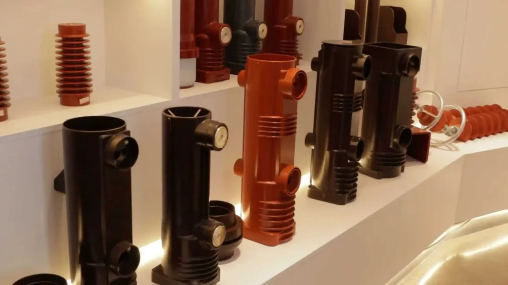
YIEOU supplies Separable Connectors and related Medium Voltage Cable Accessories for different cable connection arrangements, including elbow connectors, T-body connectors, bushings, junctions, grounding accessories, protective components, and related cable accessories.
Our goal is not simply to supply one connector body. The connector, cable, equipment interface, and related accessories should work together as one correctly matched connection system.
Conclusion
The main advantages of a Separable Connector are its insulated and shielded connection structure, removable equipment interface, compact installation, flexible network configuration, and compatibility with a range of medium-voltage accessories.
Its limitations are equally important to understand.
A Separable Connector must match the system voltage, current, cable dimensions, equipment interface, installation layout, and required operating method. Loadbreak capability only applies to connector systems specifically designed and rated for that function, while deadbreak connections must be operated after the circuit has been properly de-energized.
When these requirements are confirmed correctly, separable connectors provide a practical way to connect transformers, RMUs, switchgear, compact substations, and cable distribution systems.
For a new project or replacement connection, YIEOU can help review the cable specification, equipment interface, and required accessory arrangement so that the Separable Connector is matched to the actual medium-voltage system rather than selected only by model name or appearance.
Frequently Asked Questions
Are all separable connectors loadbreak connectors?
No. Separable connectors include both loadbreak and deadbreak designs. The operating method must follow the connector and mating interface specifications.
Can a deadbreak connector be disconnected while carrying load current?
No. A deadbreak connector should only be disconnected after the circuit has been properly de-energized and made safe according to the required operating procedure.
Are separable connectors from different manufacturers interchangeable?
Not automatically. Products must have compatible interface dimensions, ratings, contact systems, and application requirements. Similar appearance alone does not confirm compatibility.
What cable information is useful when ordering a Separable Connector?
The conductor size, cable insulation diameter, voltage rating, cable construction, and equipment interface information are particularly useful. A cable datasheet can make matching easier.
Can separable connectors be used for both radial and loop-feed systems?
Yes. Suitable separable connector systems can support radial, loop-feed, and branching arrangements. The required bushings, junctions, and number of interfaces should be selected according to the network layout.