
Quick Answer
A Separable Connector needs a cable route that allows proper alignment without using the connector body or equipment bushing to pull a stiff cable into place. Cable bending space, independent support, the direction of entry and the complete assembled depth all influence that alignment. An approved extension arrangement may help where the termination is too close to the equipment face, but it changes the assembly geometry and needs its own compatibility review.
At YIEOU, we manufacture medium-voltage cable accessories and match our assemblies to the equipment interface and cable specification. In a restricted compartment, we consider the connection position alongside the cable route. The practical aim is to give a correctly matched Separable Connector room to seat and remain supported, while preserving the access required for its intended service procedure.
A Correct Interface Can Still Be Poorly Aligned
Electrical compatibility and mechanical alignment answer different questions. Compatibility establishes whether the contact system, insulating interface and ratings belong together. Alignment describes how those compatible components meet once the cable is inside the cabinet. A Separable Connector may satisfy the first requirement while a displaced cable entry makes the second difficult.
Imagine a cable rising from below a fixed bushing. If the cable entry is too far forward, the upper cable must bend back towards the equipment. If it is too far to one side, the cable also approaches at an angle across the compartment. Both offsets can occur together. A front view may hide the forward displacement, while a side view may hide interference with an adjacent phase.
The result can be a persistent sideways force at the termination. That force may be carried by the accessory body, the conductor connection, the bushing or their supporting structures. It is different from the controlled engagement force required by the assembly instructions. A Separable Connector is designed to establish a specified electrical connection; it is not a general purpose device for correcting a poorly positioned cable route.
This is why we start a layout discussion with the bushing location and interface drawing. Moving to a smaller-looking accessory from a different system does not solve a compatibility problem. A 200A loadbreak interface, a 600A deadbreak arrangement and a 630A European-style interface remain distinct systems. Their current labels and external shapes do not establish interchangeability.
Within the appropriate equipment family, our Separable Connector assemblies can be considered together with their installed position. For example, where an underground cable terminates at switchgear through a 600A deadbreak T arrangement, the cable leg needs room below the horizontal connection. The JY TT-600 arrangement makes that relationship visible: the horizontal equipment connection and the incoming cable occupy different directions, so both belong in the layout review.
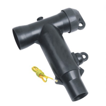
The Cable Bend Begins Before the Connector
A right-angle accessory changes the direction of the electrical connection inside its designed structure. It does not remove the need to respect the bending requirements of the cable entering it. The free cable below the Separable Connector still has to travel from the entry or support position to the cable leg without being forced into an unsuitable curve.
The cable manufacturer’s minimum bending radius is therefore an input to the layout, rather than a dimension inferred from the connector photograph. Cable construction and installation conditions affect the applicable limit. Overall diameter, conductor construction and stiffness also affect how readily the cable follows a proposed route. No universal bend radius follows from the phrase Separable Connector or from a current rating alone.
There is another distinction between a permitted bend and a useful approach direction. A cable may remain within its bending limit yet arrive at the termination at an awkward angle. The relevant question is whether the final portion can enter the accessory as required by its instructions while the preceding curve fits the cabinet. Simply drawing a large enough arc somewhere below the bushing does not establish that result.
Cable length influences this geometry too. A cable cut too short can leave little freedom to form a suitable approach. Extra length is not automatically beneficial either: it may create a loop that presses against another phase, a door or a compartment wall. The intended route and preparation dimensions establish the useful length, rather than an arbitrary allowance added to every termination.
For a Separable Connector layout, the bend and the cable entry are best viewed as one continuous route. The cable approach links the fixed entry and the termination, so a change at either end can affect the bend between them.
Support Carries the Cable While the Interface Makes the Connection
A cable support and a termination contact serve different purposes. The support manages the cable’s position and mechanical loading. The contact and insulating body establish the connection at the prepared cable end. Using the connection itself to hold the cable in its intended route combines these jobs in a way that can leave the interface under sustained strain.
The position of a Separable Connector cable support matters as much as its presence. A clamp that fixes the cable on the wrong line may preserve the very offset that causes difficulty at the bushing. A support far from the termination may leave a long unsupported section. The suitable arrangement depends on the cable, equipment and accessory requirements, so a single clamp spacing cannot be applied to every cabinet.
Similarly, a cable gland at the compartment entry is not automatically a substitute for the required cable support. Some entry arrangements provide specified restraint, while others mainly seal the opening. The equipment design determines which components carry the cable load. That distinction helps explain why a Separable Connector may still be under strain even when the entry looks firmly closed.
Cable restraint also has to be considered for the installation’s mechanical duty, including any specified short-circuit forces. This belongs to the equipment and cable support design. A connector current rating does not define the strength of a cleat or its fixing structure. We keep that responsibility separate when discussing the accessory arrangement with switchgear manufacturers and project engineers.
For the connection itself, the useful outcome is straightforward: the prepared cable can meet the intended interface without the body being used to drag it into position. The actual support location and assembly sequence come from the applicable instructions. Tightening hardware beyond its specified requirement is not a remedy for a displaced cable route or a loaded Separable Connector.
Extra Stand Off Can Help a Difficult Cable Route
Sometimes the cable route is constrained by a fixed floor opening while the termination sits very close to the apparatus face. In that situation, moving the Separable Connector position forward may create a more workable approach. The change is in the position of the complete assembly, rather than in the flexibility of its insulation body.
Our JY TTL deadbreak connector plug is relevant to this situation because it is used to connect compatible 600A deadbreak terminators and, with a bushing extender, can increase the distance between the apparatus front plate and the terminator. That additional distance can ease cable training, meaning the arrangement of the cable into its required route. Its usefulness follows from the geometry of the application.
The extension is still a defined part of the Separable Connector system. It is not a generic spacer that can be inserted between any two similar-looking components. The mating interfaces, contact arrangement, voltage class and complete assembly have to match. An available extension in one product family does not establish an equivalent option for another family.
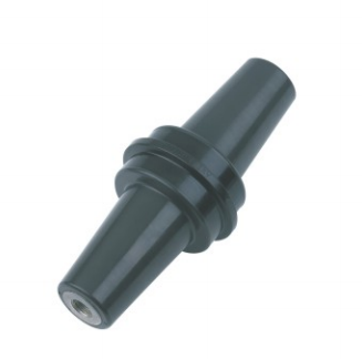
Moving a termination forward also consumes space. It may improve the cable approach while reducing clearance to the door, another accessory or the working area in front of the equipment. The new arrangement can also change the relationship between the termination and its support. For that reason, added stand off is assessed in the full side view, together with the cable route and access envelope.
An extension cannot make a cable exceed its permitted bending limit, carry unsupported cable weight or correct the wrong equipment interface. It is useful when a specific displacement improves an otherwise compatible Separable Connector arrangement. Whether it is the appropriate solution depends on the complete assembly drawing and the constraints that caused the alignment problem.
Compare Layout Changes by the Problem They Address
Several changes can make a compartment appear more spacious, but they do not solve the same problem. Moving the entry changes where the cable arrives. Adjusting an approved support arrangement changes where it is restrained. A compatible extension changes the position of the connection itself. Comparing those effects helps avoid adding components when the route is the actual difficulty.
Table 1. Layout conditions and their connection implications
| Layout condition | Effect on the connection | Useful direction for review |
|---|---|---|
| Cable entry offset from the bushing | Cable approaches the termination sideways | Entry position and the complete cable route |
| Tight bend immediately below the body | Cable cannot approach in the intended direction | Cable bending requirement and available height |
| Support fixes the cable away from its natural approach | Persistent load remains at the interface | Support location within the approved equipment arrangement |
| Termination too close to the apparatus face | Limited room to train the incoming cable | A compatible extension arrangement and its assembled depth |
| Door closes but tools cannot reach the connection | Installed fit leaves insufficient service access | Required access and movement around the full assembly |
For an OEM cabinet review, these are different design questions even when the visible symptom is the same. A Separable Connector that is difficult to position may need a route adjustment, a compatible accessory arrangement or a change in the cabinet provisions. Selecting among those options requires identifying where the restriction originates.
A useful Separable Connector comparison includes the original and proposed connection positions on the same drawing. The bushing centreline, cable entry, support and door position provide a common reference. This makes the effect of each change visible. It also prevents an improvement in one view from hiding a new obstruction in another.
Internal Fit Still Matters When the Outside Looks Straight
Correcting the Separable Connector cable route does not establish that the cable fits inside the accessory. A Separable Connector also depends on the relationship between the conductor contact, insulation interface and stress-control region. Those features require the cable dimensions and preparation specified for the selected kit.
Conductor cross-section and diameter over insulation describe different parts of the cable. The contact must suit the conductor material, size and construction, while the insulating body or specified adapter must fit the relevant insulation diameter. A cable can have an acceptable overall route and still require a different contact or cable adapter. Mechanical alignment cannot compensate for an incorrect internal fit.
The distinction is easier to understand in a screened deadbreak assembly. In our JY TIIT-600 construction, the conductor terminal, insulating layer, stress-control features and conductive outer layer have separate roles. The copper or copper-aluminium terminal selection relates to the cable conductor, while the outer conductive layer forms part of the screened arrangement. Pulling the cable sideways does not improve any of these relationships.
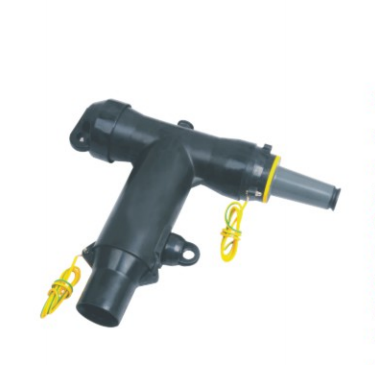
Connector geometry includes more than the visible outline. Two bodies can appear similar while placing the conductor contact or cable interface differently. That is why preparation dimensions from one assembly cannot simply be carried over to another, even when their external shapes look familiar.
The earth connection for the conductive screen also needs an appropriate route. It has an electrical purpose and cannot serve as a tie to restrain the power cable. A Separable Connector installation therefore brings together cable fit, screen continuity and mechanical support, while keeping each component’s function clear.
Service Access Is Larger Than the Installed Outline
A completed Separable Connector occupies one envelope; accessing it can require another. The space needed for tools, specified removal movement and handling of the cable may extend beyond the body visible in the installed drawing. A cabinet door that closes is useful evidence of physical containment, but it says little about whether the connection can be serviced as intended.
The access review follows the actual Separable Connector system. A deadbreak assembly does not become a load switching device because it is removable. Work on it requires the appropriate de-energized condition and approved procedures. Likewise, a loadbreak design has defined operating conditions and equipment requirements; extra room in front of it does not create unrestricted permission to disconnect it.
For a compact T-body arrangement, nearby accessories may block a tool path even when they do not touch the body. Cable supports can also obstruct the movement needed during the prescribed service procedure. Considering these relationships before the enclosure is finalized helps distinguish a compact installation from one that is difficult to access.
The three phases deserve attention together. A route that works for the outer cable may not fit the middle phase once neighbouring bodies, screen leads and supports are present. A Separable Connector arrangement is therefore reviewed as an installed group, with the actual phase positions and available access, rather than as one isolated product outline repeated across the drawing.
Resolve the Route and Connection Together
The most useful starting information is often a bushing drawing, a cable datasheet and a side view of the compartment showing the entry and support positions. Photographs can clarify the physical setting. The dimensional drawing establishes relationships that perspective can hide, especially the distance from the apparatus face to the cable centreline and the door.
We can use the available information to discuss our Separable Connector options and the relevant cable or interface details. If a compatible extension could improve the approach, it belongs in the same review as the revised support and service space. The resulting assembly can then be checked against the actual equipment arrangement before repeat supply is agreed.
A well-matched Separable Connector brings the cable to the interface in its intended position. At YIEOU, we match our accessories to that physical and electrical relationship as part of our OEM project support, so that compact installation does not depend on forcing the cable or connection into place.
FAQ
Can a Separable Connector support the weight of the cable
Cable support must follow the equipment, cable and accessory requirements. The connector or bushing should not be assumed to carry unsupported cable weight simply because the assembly remains connected. A suitable support arrangement also controls the cable’s approach to the termination.
Does a right angle body remove the cable bending requirement
No. The accessory turns the connection within its designed structure, but the incoming cable still needs its permitted bend and approach. The cable manufacturer’s applicable bending requirement remains part of the layout.
Can an extender solve a tight cable compartment
It can help when moving a compatible termination away from the apparatus face improves the cable route. It also increases assembled depth and may reduce door or service clearance. The complete arrangement determines whether the change is useful.
Why can matching cable sizes still produce different layouts
Nominal conductor area does not describe overall diameter, insulation diameter or stiffness. Changes in cable construction can affect both the internal fit of a Separable Connector and the route needed to reach it. These are related but separate checks.
Is the layout acceptable if the cabinet door closes
Door closure confirms only one part of the installed space. Cable bends, support, adjacent phases and the specified service access still matter. The connection also needs to reach its intended position without sustained side loading.
Does adding an extension change deadbreak operation
No. A compatible extension changes the assembly arrangement, not the deadbreak operating principle. The Separable Connector remains subject to its specified ratings and approved de-energized service procedures.