
The cable room in a commercial development often serves several buildings with different operating hours. Shops may close before restaurants, office tenants may work late, and shared services can remain in use throughout the night. When a transformer or switchgear panel needs attention, the cable connection affects how that work can be carried out within the available space. A Separable Connector provides a removable connection between a medium-voltage cable and compatible equipment. In a development supplied through 35 kV European-style equipment, its practical value depends on the cable route, the equipment terminals and the access that remains after the building is occupied.
Quick Answer
A commercial building needs a 35 kV Separable Connector where the specified medium-voltage equipment has a matching separable interface. It can be useful at transformer connections, switchgear cable entries and designated branch points serving different parts of a development. The Separable Connector must fit both the equipment bushing and the actual cable, with enough room to install and later remove the complete assembly.
At YIEOU, we manufacture screened European-style cable accessories for these connections. Our Separable Connector configurations include front connections, matching rear connections and cable branching components. The choice follows the job at each location: connecting a feeder to equipment, accommodating another cable or forming a planned branch. For building contractors and equipment manufacturers, the important question is how that connection will work inside the finished electrical room.
One Intake Can Serve Several Different Building Areas
In a shopping and office development, the incoming medium-voltage cable may reach a central intake room before feeders continue to separate transformer locations. A connection beside the main switchgear faces different space and access conditions from one inside a compact substation at the edge of the site. Looking at these positions separately makes it easier to choose a workable Separable Connector and enclosure arrangement.
At a transformer connection, a Separable Connector allows the cable to terminate at a defined equipment interface. That becomes useful when the transformer eventually needs replacement: the cable connection can be separated at the terminal rather than treating the cable and transformer as a permanent assembly. Enough sound cable length and a usable approach to the bushing are still needed to reconnect the equipment.
Between buildings, a designated distribution enclosure may bring several cable routes together. Here, the connection layout needs to reflect the way the cables arrive from the ground and continue towards each building. A branch facing the wrong direction can create unnecessary crossing and tight bends even when the enclosure appears large enough. The practical benefit comes from placing the connection where the cable can approach it naturally.
The incoming voltage is established by the development’s supply arrangement. A tower, retail block or large transformer does not by itself establish a 35 kV requirement. Once the voltage and equipment interface are known, the Separable Connector can be matched to that location. This keeps the choice connected to the actual installation rather than to assumptions about the size or importance of the building.
Room Layout Can Decide Whether a Connection Is Usable
Cable compartments often look spacious before the feeder cables are installed. The difference becomes apparent when a stiff cable rises from a trench and has to turn towards a low-mounted bushing. The connector body occupies only part of that space. The cable bend, the support position and the approach needed to assemble the connection can take considerably more room than the terminal shown on an equipment drawing.
A Separable Connector at a low bushing may fit best when the trench entry is aligned with the connection. If the cable emerges to one side, pulling it across the compartment can place persistent sideways force on the joint. A support positioned close to the equipment can carry the cable while preserving the required bend. The accessory then forms the electrical connection without also carrying the weight of the feeder.
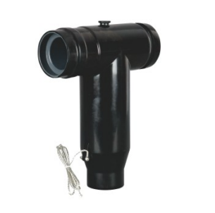
Where a European-style front connection is specified, we offer moulded EPDM bodies with a semiconductive screen. For example, our JY TT-35/630A front connector fits the corresponding 35 kV equipment arrangement. In a building cable room, the useful feature is the screened connection at the bushing. Its installed position still needs room around the cable entry and access for the work needed to separate it during a planned outage.
Access also changes as construction progresses. A connection installed before the adjacent panel may be easy to reach from the side. Once that panel and its cables are in place, the same approach may disappear. A Separable Connector layout therefore needs to remain workable in the completed lineup, with doors open and all neighbouring equipment installed. Checking the finished arrangement prevents a compact installation from becoming an inaccessible one.
In developments using equipment from different sources, similar-looking terminals can conceal different mating arrangements. The Separable Connector has to match the bushing profile, conductive contact and insulation interface at each panel. A 600 A American deadbreak connection and a 630 A European connection cannot be exchanged on the basis of their current ratings. This matters during equipment replacement, when a new panel may introduce a different interface into an otherwise unchanged room.
Replacing Switchgear Can Change the Fit of an Existing Cable
A commercial refurbishment may retain the incoming feeder while replacing the switchgear around it. The cable may have enough electrical capacity for the continued service, yet the new equipment can put its terminals higher, lower or farther from the trench. That change affects how much cable reaches the connection and how sharply it must bend. The old termination position is therefore a useful physical reference, rather than a guarantee that the new arrangement will fit.
The cable side of a Separable Connector needs the same attention as the equipment side. Two cables with identical conductor cross-sections can have different diameters over insulation. The accessory has to fit the prepared insulation properly, while its conductor contact suits the conductor material and construction. Matching only the nominal cable size can leave one of these connections incorrect.
An existing feeder can also have limited spare length. Removing an old termination and preparing a fresh connection consumes cable, and the available insulation must be in suitable condition at the new termination position. If the replacement bushing is farther away, forcing the cable into place can compromise both the bend and the support arrangement. A workable retrofit resolves that geometry before the connection is assembled.
We configure the cable-side components of our front and rear accessories for the applicable cable dimensions. For a Separable Connector used in refurbishment, this means the equipment interface and cable fit are established separately, then brought together in the final assembly. The configuration can accommodate a compatible new terminal without assuming that the old cable preparation can simply be repeated.
Even when the equipment stays in the same room, its cable entry direction may change. A cable previously entering from below may need to approach a differently positioned terminal. The replacement enclosure, cable support and connector orientation all influence whether that route remains practical. These physical details can determine whether a retained feeder is straightforward to reconnect or needs a different connection arrangement.
A Second Cable Changes More Than the Number of Terminals
In a development with several buildings, a distribution point may need an additional cable connection. The available arrangement depends on the equipment and the intended network. Where a matching front connection permits it, a rear connector can accommodate another cable. The Separable Connector assembly extends farther into the compartment, so the extra cable changes both the assembly depth and the routes around it.
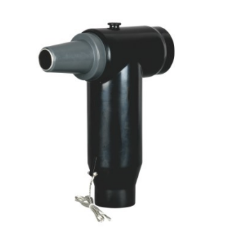
For this arrangement, our JY HTT-35/630A rear connector mates with the corresponding European-style front connection. In a narrow building cable room, the useful comparison is between the complete front-and-rear assembly and the space available behind the closed equipment door. Measuring only the original front connector can overlook the depth needed for the additional body, its cable and its support.
The two cables may arrive from different trench positions. If one passes across the other connection, accessing the rear assembly can become awkward during later maintenance. A Separable Connector layout works better when each cable has a clear approach and can remain supported while the relevant connection is accessed. The intended arrangement also needs to respect the equipment’s provisions for additional cables.
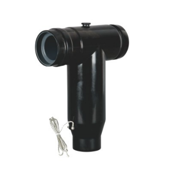
At a separate distribution enclosure, T-type branching can bring a feeder and its planned branch together. We manufacture a 35 kV T cable connector for compatible European-style cable branching arrangements. This can suit a designated connection point between building areas, where the cable routes and associated switchgear are arranged for that function. The enclosure needs room for the installed branch and for each cable bend.
Table 1. Practical connection arrangements in a commercial development
| Building situation | Connection arrangement | Space or access consequence |
|---|---|---|
| Feeder entering a transformer or switchgear panel | Front connector on a matching equipment bushing | Keep a direct cable approach and access around the terminal. |
| Additional cable at compatible equipment | Approved front-and-rear assembly | Allow for added depth, two cable routes and their supports. |
| Feeder dividing at a designated distribution point | Compatible T-type branching component | Provide an enclosure that accommodates all branch cable bends. |
| Future building phase awaiting connection | Protected spare interface and reserved cable route | Keep both the interface and its future cable approach accessible. |
An extra cable does not increase the rating of a shared bushing or conductive path. Its current duty remains part of the complete equipment arrangement. Likewise, the Separable Connector makes the cable connection, while the associated switchgear provides the required switching and protection. These duties become especially important when different building areas are intended to be isolated independently.
Construction Dust and Room Moisture Reach Different Parts of the Connection
Commercial electrical equipment can be installed while finishing work continues nearby. Dust from cutting, drilling and building services can enter an open cable compartment before commissioning. A Separable Connector needs clean mating surfaces and properly prepared cable insulation. Keeping construction contamination away from these surfaces is more effective than relying on the outside of the completed connector to hide what entered during assembly.
Cable openings also connect the equipment room to a different environment. Moist air from a trench can enter a cooler room, while water at an external cable route may collect near the building entry. The cabinet, entry seals and room conditions all affect what reaches the connection. The actual exposure at that position matters more than a general description such as indoor installation.
Our 35 kV front and rear accessories combine EPDM insulation with a semiconductive screen and specified sealing protection. In service, the Separable Connector cable-side fit and the equipment-side mating surface must both remain correctly assembled. A sealed connector body cannot stop water entering through an unrelated cabinet opening or prevent condensation on surrounding components. Those routes need attention at the enclosure and room level.
For a Separable Connector in a damp electrical room, condensation deserves particular consideration because it can develop without visible water leakage. The standard service conditions for our front connector specify non-condensing humidity. A room that repeatedly develops moisture on equipment surfaces needs its environmental conditions addressed rather than being treated as suitable simply because the accessory carries an IP67 rating.
The screen and grounding connections also need a clear route inside the compartment. A screened Connector relies on the intended grounding arrangement to maintain its designed condition. Grounding leads need protection from cable movement and interference with doors or adjacent fittings. Keeping these connections accessible makes their condition easier to assess during planned equipment inspections.
Maintenance in an Occupied Development Depends on Access
An electrical room that was convenient during construction can become crowded after several tenant fit-outs. New containment, control cables or stored materials may occupy the space around the medium-voltage equipment. The Separable Connector remains removable only if the equipment can still be opened and the cable connection reached. Preserving that access is part of keeping the installed connection useful over time.
For example, replacing a transformer may require the cable to be detached while the feeder remains in its established route. If the connector is trapped behind an unrelated cable tray, the work can expand beyond the transformer connection itself. A clear approach to the bushing and adequate supported cable length make the original separable arrangement more practical when equipment eventually changes.
In a commercial complex with evening trading or shared services, maintenance access can be limited to a planned outage period. A Separable Connector cannot determine how much of the development can remain supplied. That depends on the switching and protection arrangement. Its contribution is a defined cable connection that can be accessed once the equipment has been correctly isolated and verified for the work.
Alternative supplies and ring arrangements require particular care because an open device on one side may not remove every possible source. The European-style connections used for these applications are separated under the applicable de-energised working procedures by qualified personnel. Their removable construction supports maintenance after isolation; it does not provide load switching at the cable joint.
The support arrangement matters during that work as well as in normal operation. The cable needs to remain controlled when the connection is separated, without transferring its weight to another terminal or grounding lead. A Separable Connector positioned with its cable support and maintenance approach in mind is easier to work around than one fitted into the last available gap.
Leave a Real Cable Route for the Next Building Phase
A commercial estate may add another building or transformer after the first phase is occupied. Reserving a spare interface is useful, but the future feeder still needs a route into the enclosure. A later wall, panel extension or cable tray can occupy that space. The planned Separable Connector position and its cable approach need to remain available together.
An unused Separable Connector interface requires matching insulation suitable for its installed service condition. Transport protection is intended for a different purpose. Around the protected interface, enough space needs to remain for the future cable bend, support and completed assembly. This gives the later connection a practical installation position without disturbing unrelated building feeders simply to reach it.
At YIEOU, we manufacture front, rear and branching accessories with dimensional and electrical verification, including high-voltage and partial-discharge testing as applicable. For commercial equipment, these product checks support the interface and insulation requirements, while the finished installation brings the cable fit, support and environment together. Keeping those details aligned gives our Separable Connector configurations a useful role from initial construction through later equipment replacement and expansion.
FAQ
Does a large commercial building automatically need a 35 kV Separable Connector?
No. The supply voltage and equipment interface determine the required accessory. Building size or transformer capacity alone cannot establish the connector voltage or mating arrangement.
Can an existing feeder be retained when the switchgear is replaced?
It may be possible if the cable remains suitable for the service and has enough sound length for the new terminal position. The cable dimensions, preparation location, bend and support all affect the new connection.
Why can a rear connector be difficult to fit in an existing compartment?
It adds depth to the front connection and introduces another cable route. The complete assembly, cable bends and supports need space behind the closed door and access for later work.
Is conductor cross-section enough to match a Separable Connector?
No. Diameter over insulation, conductor material and construction also affect the cable-side fit. The equipment bushing remains a separate compatibility requirement.
Does an IP67 connector solve moisture problems in a cable room?
The enclosure, cable entries and room conditions still need appropriate protection. Condensation on equipment surfaces needs attention even when the connector assembly is correctly sealed.
Can these connections be separated while the building feeder is carrying load?
The 35 kV European-style connections require the applicable isolation, de-energisation and verification procedures before separation. Load switching belongs to the designated switchgear, not the detachable cable connection.