
Data center campuses are adding larger utility services, more transformer capacity, and more medium-voltage switching points as computing loads grow. The cable connection inside each RMU, switchgear lineup, prefabricated substation, or transformer enclosure can look like a small part of that expansion, but it determines whether the selected cable can actually mate with the equipment. A Separable Connector for this application has to fit the bushing interface, voltage class, current class, cable construction, and physical layout. The same checks also matter when a campus is expanded in phases and new feeders must connect beside equipment that is already in service.
Quick Answer
A Separable Connector for data center medium-voltage distribution should be selected from the equipment interface outward. First identify the bushing system and whether it belongs to a 600A American-style deadbreak arrangement, a 630A European-style external-cone arrangement, or another defined interface. Then match the system voltage, connector duty, conductor material, cable cross-section, diameter over insulation, and compartment space.
At YIEOU, we manufacture medium-voltage cable accessories for American- and European-style connection systems. In data center projects, we treat the Separable Connector, equipment bushing, cable adapter, conductor contact, shielding, grounding, and cable route as one connection system. Similar current ratings or similar T-shaped bodies do not establish compatibility.
Begin With the Actual Equipment Bushing
Data center power distribution often uses repeated electrical rooms or modular power blocks. That repetition can make a Separable Connector schedule appear simple, but the equipment interfaces may still differ between utility switchgear, campus RMUs, transformer primary compartments, and packaged substations. The bushing drawing is therefore the strongest starting point for Separable Connector selection.
The drawing should identify the interface geometry, voltage class, continuous current class, and any applicable equipment standard. A product described only as a 15kV or 24kV T-body is not specific enough. Two connectors can share a voltage label and a similar external outline while using different mating dimensions, contact arrangements, or accessory systems.
For European-style equipment, a screened 630A front connector may be designed for a standardized external-cone bushing. For American-style equipment, a 600A deadbreak connector belongs to another interface family. The difference between 600A and 630A is not a ten-ampere purchasing choice. It usually indicates a different equipment system, and the selected Separable Connector must stay within that system.
This interface-first approach is particularly useful when a project includes equipment from more than one OEM. A campus specification may define the same nominal system voltage across the site, yet the transformer and switchgear packages can arrive with different bushing systems. Recording the interface at each cable termination avoids turning a site-wide voltage schedule into an incorrect site-wide Separable Connector assumption.
Our Separable Connector range includes European-style front and rear connector arrangements for defined equipment and cable combinations. The Separable Connector family is chosen from the real bushing and cable data rather than from the application name alone.
Redundant Feeds Change the Connection Layout
Data center electrical systems often separate power paths so that maintenance or a single equipment event does not remove every supply route to a critical load. The topology is determined by the project designer, but it directly affects the Separable Connector layout inside the medium-voltage equipment. A radial transformer feed, a loop arrangement, and a dual-cable connection do not use the same number or position of cable interfaces.
A front connector can provide the primary cable-to-equipment connection. When the compatible product system supports it, a rear connector can extend the same connection position for a second cable path or another defined accessory. This arrangement is useful only when the equipment bushing, front connector, rear connector, and cable layout were designed to work together. A rear port should not be treated as a universal spare connection.
The current path also needs a clear rating basis. Two connected cables do not automatically double the current rating of an equipment bushing or Separable Connector interface. Each component retains its own rated limits, and the switchgear or transformer connection point remains subject to the equipment design. Parallel cable operation, loop-feed operation, and a normally open standby feed are different electrical arrangements even if two cables are visible in the same compartment.
Expansion planning should therefore identify the intended state of every interface. A future cable position may remain de-energized and capped during the first construction phase. Another position may be part of an energized loop from the first day. The Separable Connector system needs the correct rear accessory, insulation cap, grounding provision, or surge protection component for that intended state.
This is where Separable Connector selection supports modular construction. Repeating a verified equipment-interface and cable-accessory package across identical power blocks can reduce variation. The repeatable unit is the complete matched connection, not a generic T-body description copied between equipment packages.
European 630A Front and Rear Connectors Need One Matched System
A European-style 630A arrangement can suit compact RMUs, cable branch equipment, and prefabricated substations used in data center distribution. The front connector mates with the equipment bushing and terminates the cable. A compatible rear connector may attach behind the front connector when the design requires another cable connection or accessory position.
For example, our JY JB-15/630A European front connector is intended for 15kV, 630A cable connections in European-style equipment. The official product data lists EPDM construction, a fully screened detachable structure, and an applicable cable cross-section range of 25 to 400 mm². That range is a product-family boundary, not a complete cable selection rule. The actual cable adapter and contact still depend on the cable insulation diameter and conductor details.
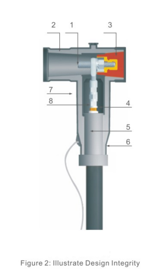
The JY HJT-24/630A rear connector serves a different position in the connection. It is a 24kV, 630A European-style rear connector used with a compatible front connector. Its product data also lists a 25 to 400 mm² cable range and an IP67 fully screened structure. The voltage class, interface, cable data, and front-connector compatibility all have to agree before it can be used.
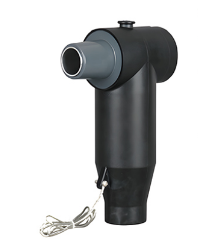
Front and rear products should not be mixed simply because both are described as 630A. A 15kV front connector does not by itself prove compatibility with a 24kV rear component, and the rear interface provided by one front connector may not accept every rear accessory. The complete assembly needs a verified product combination and an equipment interface rated for the intended arrangement.
The rear connection also changes the physical envelope. It adds depth behind the front connector and may place another cable closer to the compartment wall, neighboring phases, or cable-entry plate. In a compact power module, the electrical match can be correct while the installed cable route is still impractical. Separable Connector drawings and cable bend requirements should be checked on the same compartment view.
A 600A Deadbreak System Is a Different Interface Family
Some data center projects use American-style medium-voltage equipment, particularly where the utility, transformer package, or established campus standard is based on 600A deadbreak interfaces. This system can also use T-shaped cable connections, but it should not be combined with the European 630A system by appearance or current rating.
Our JY TT-600 product family is a 15kV or 24kV class 600A deadbreak cable termination for compatible apparatus. The official product information identifies a conductor cross-section range up to 500 mm² for the 24kV cable configuration and an optional capacitive test point. The exact order selection still depends on the voltage class, cable dimensions, conductor, and interface configuration.
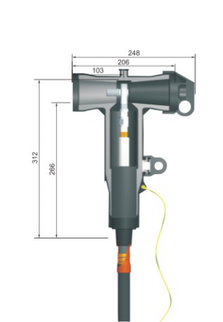
Deadbreak describes the operating duty of the connection. It is not a load-switching device and should not be disconnected while carrying load current. The switchgear, circuit breaker, or other approved switching device performs the circuit operation. Work on the Separable Connector follows the isolation, verification, grounding, and operating procedure for the complete installation.
Accessory compatibility also stays within the 600A system. T-body plugs, bushing extenders, protective caps, grounding accessories, and surge arrester positions have defined mating relationships. A component that fits a 200A loadbreak system or a 630A European external-cone system is not a substitute because it has a similar purpose.
The distinction can be summarized in the equipment interface. A Connector needs a defined mating geometry and contact relationship. At medium voltage, the insulation interface, stress control, shielding, and grounding arrangement add further requirements that make visual comparison insufficient.
Table 1. Data Center MV Connector System Boundaries
| Selection point | European-style 630A arrangement | American-style 600A deadbreak arrangement |
|---|---|---|
| Typical equipment context | European-style RMU, switchgear, cable branch equipment, or prefabricated substation | American-style switchgear, transformer, cable branch equipment, or prefabricated substation |
| Equipment interface | Defined external-cone bushing and matching front connector system | Defined 600A deadbreak bushing interface |
| Extension approach | Compatible rear connector or accessory behind the front connector when the system permits | Compatible T-body plug, extender, cap, arrester, or other 600A accessory |
| Operating duty | Connector remains the cable interface while equipment performs switching | Deadbreak connection is operated only after the circuit is properly isolated |
| Cable information | Voltage class, conductor, cross-section, diameter over insulation, screen construction | Voltage class, conductor, cross-section, diameter over insulation, screen construction |
| Interchangeability | Not interchangeable with a 600A American-style system | Not interchangeable with a 630A European-style system |
Cable Construction Determines the Final Kit
The equipment bushing identifies the Separable Connector family, but the cable determines the parts inside the cable-side assembly. Data center feeders can differ by conductor material, conductor construction, screen design, insulation material, and manufacturer even when their voltage and cross-section labels match.
Cable cross-section is only one input. A 240 mm² copper cable and a 240 mm² aluminum cable can require different conductor contacts. Two XLPE cables with the same conductor size can have different diameters over insulation. That diameter governs the cable adapter or stress-control fit, so it needs to be taken from the actual cable datasheet or a controlled measurement rather than inferred from the conductor size.
The screen construction also affects preparation and grounding. Copper wire screens, tape screens, and other designs need the correct restoration and grounding arrangement around the connector. The Separable Connector body provides the designed electrical interface only when the cable preparation preserves the required insulation surface, semiconductive transition, stress-control region, and screen continuity.
The cable schedule should therefore connect each termination point with its real cable designation. A campus may use one cable family between the utility service and main switchgear, another between switchgear and transformers, and a smaller feeder for an auxiliary power block. Applying one adapter code to all three because they share a nominal voltage can create an incorrect fit.
At YIEOU, our product range includes Separable Connector bodies, cable adapters, conductor contacts, rear connectors, caps, and related accessories for specific interface systems. We manufacture these components as coordinated product families. Model selection remains tied to the bushing and cable combination at each termination point.
Table 2. Information That Changes the Separable Connector Configuration
| Project detail | What it controls in the connection |
|---|---|
| Equipment bushing drawing | Connector family, mating geometry, and current-class interface |
| System voltage and maximum operating voltage | Insulation class and compatible product range |
| Conductor material and construction | Copper or bimetallic contact selection and crimping arrangement |
| Cable cross-section | Narrows the contact and adapter range but does not complete the selection |
| Diameter over insulation | Determines the cable adapter and stress-control fit |
| Cable screen design | Affects preparation, screen continuity, and grounding details |
| Front, rear, or accessory position | Determines the connector body and compatible extension component |
| Compartment drawing and cable entry | Confirms installed depth, phase spacing, bend radius, and cable support |
Compartment Space Must Be Checked With the Cable Installed
Data center power rooms often favor compact equipment and repeatable skid layouts. A dimensionally small switchgear panel can still require substantial working space below or behind the bushing because medium-voltage cable does not bend at the Separable Connector face. The cable route should approach the Separable Connector without forcing the body to carry bending load.
The relevant envelope includes the Separable Connector body, rear accessory, cable adapter, grounding lead, cable bend, cleats, gland plate, and any neighboring phase. A front connector may fit comfortably by itself, while a rear connector and second cable push the assembly into a wall or door zone. The installation drawing should show the connector in its final orientation with the cable bend and support points.
Cable weight matters as well. Vertical cables entering from a trench or raised floor need support so their weight does not pull on the Separable Connector interface. Horizontal routes need cleats positioned to maintain alignment without creating a sharp bend close to the stress-control region. Support design belongs to the equipment and cable installation, but the Separable Connector drawing defines the zone that must remain free of mechanical strain.
Phase arrangement affects access. A technician needs enough room to prepare the cable, make the conductor connection, apply the adapter, seat the Separable Connector, and complete grounding without damaging adjacent phases. The connector should not be rotated into place by twisting the cable beyond its acceptable torsion. If the assembly requires a rear accessory, its installation sequence also needs to be possible inside the available compartment.
Factory-built power modules provide an opportunity to validate this layout before shipment. A representative cable and the actual Separable Connector components can reveal conflicts that are not obvious in a two-dimensional bushing schedule. The result should confirm a practical installed position, not merely that the Separable Connector outline fits within the enclosure boundary.
Commissioning and Maintenance Depend on Identifiable Interfaces
A data center campus may contain many visually similar cable compartments. Clear identification becomes important when one power block is commissioned, another is expanded, and a third remains in service. Each Separable Connector position should be traceable to its equipment interface, cable, voltage class, and Separable Connector model.
This record supports spares without encouraging false interchangeability. A site may keep separate spares for a 600A American-style deadbreak system and a 630A European-style system even when both serve equipment at the same nominal voltage. Combining them under one generic “MV T-connector” stock description can lead to the wrong body, adapter, contact, or accessory being issued during an outage.
The same discipline applies to front and rear components. A rear connector is associated with a particular compatible front connector and cable configuration. Protective caps and grounding accessories also need exact interface identification. Spare parts should preserve the product-system relationship that was verified for the installed connection.
Condition checks should focus on relevant observations: connector seating, grounding continuity, cable support, contamination, mechanical damage, and signs of abnormal heating or discharge. These observations help identify whether the connection needs further investigation. They do not authorize live manipulation of a deadbreak connector or replacement with a component from another interface family.
Where a capacitive test point is included, its intended instrument and operating procedure should be recorded. A test point may support voltage indication, phase comparison, or a compatible fault indicator, depending on the product design. It does not change the connector duty and should not be confused with a direct high-voltage test terminal.
Specify the Complete Connection Rather Than a Generic T Body
A useful data center connector schedule identifies the termination point and the complete component relationship. The equipment bushing comes first, followed by the Separable Connector body, cable adapter, conductor contact, rear component or cap, grounding provision, and any specified indication or surge-protection accessory.
The schedule should also separate equipment packages. A main switchgear feeder may use a 24kV 630A European-style connector, while a transformer package elsewhere on the campus uses a 15kV 600A American-style deadbreak connection. Keeping these lines distinct prevents the common mistake of standardizing the product name while ignoring the interface.
Model details should remain proportional to the decision. The JY JB-15/630A front connector illustrates a 15kV European-style cable-to-equipment position. The JY HJT-24/630A rear connector illustrates a compatible rear-cable position in a 24kV European-style arrangement. The JY TT-600 illustrates an American-style 600A deadbreak cable termination. These examples explain product roles; they are not a universal bill of materials for every data center.
Our Separable Connector and European cable accessory families cover different interface systems and accessory positions. We manufacture the matching components within each family and keep the 600A deadbreak and 630A European-style boundaries explicit. That makes the product specification easier to repeat across identical power blocks without assuming that unlike equipment packages use the same connection.
Data center growth makes repeatable medium-voltage connections valuable, but repeatability begins with a verified interface. The correct Separable Connector follows the equipment bushing, voltage and current class, cable construction, insulation diameter, connector position, and installed cable route. European 630A front-and-rear systems and American 600A deadbreak systems can both serve compact medium-voltage distribution, but they remain different product families. A complete connection schedule preserves those boundaries while allowing a proven package to be repeated where the equipment and cable data are genuinely the same.
Frequently Asked Questions
Which Separable Connector is suitable for a data center RMU?
The suitable product depends on the RMU bushing interface, system voltage, current class, cable construction, and compartment layout. A 630A European-style connector may suit a defined external-cone interface, while a 600A American-style deadbreak connector requires its own matching bushing system.
Can 600A and 630A T connectors be interchanged?
No. The current ratings may look close, but the equipment interface, standards, contact arrangement, and accessory system can differ. Compatibility must be confirmed from the actual bushing and product data.
Does a rear connector automatically provide a redundant feed?
No. A rear connector provides a physical connection position within a compatible system. Whether the second cable is a loop feed, parallel path, standby feed, or another arrangement is determined by the approved electrical design and equipment rating.
Is cable cross-section enough to select the cable adapter?
No. Cable cross-section narrows the range, but diameter over insulation, conductor material, conductor construction, insulation type, and screen design also affect the final kit.
Can a 600A deadbreak connector be disconnected under load?
No. A deadbreak connector is handled only after the circuit has been properly isolated according to the system procedure. The switchgear or other approved switching device performs load switching.
Why must connector depth be checked in a modular power room?
The installed envelope includes the connector, rear accessory, cable bend, grounding lead, and cable support. A body that fits on the bushing can still conflict with a wall, door, neighboring phase, or required cable bend.
What should be included in a data center connector spare list?
Spare records should identify the exact interface family, voltage class, connector model, cable adapter range, conductor contact, and compatible caps or rear accessories. American 600A and European 630A parts should remain separate even when they serve the same campus voltage.