
A heat pump added to an existing heating plant brings a new electrical connection into a space already occupied by pipes, pumps, and operating equipment. The transformer may stand outside, the medium-voltage switchgear may remain in an older building, and the cable route may cross an area that must stay accessible throughout the heating season. The connection between that cable and the equipment deserves attention while those positions are still being decided. At YIEOU, we manufacture Separable Connector accessories for equipment manufacturers and engineering contractors integrating these connections into working heating plants.
Quick Answer
A Separable Connector can suit the medium-voltage equipment supplying a large heat pump plant where the equipment has a matching separable bushing interface. We manufacture cable accessories for defined American- and European-style connection systems. Their role is to connect the MV feeder at equipment such as a transformer, ring main unit, or cable branch enclosure; the connection arrangement depends on that equipment and the actual cable.
For heating projects, the practical priorities are a connection that fits the selected equipment, an installed cable route that remains manageable beside the heating plant, and access for planned work. We distinguish the main plant supply from smaller auxiliary transformer branches because their connection duties can differ. Neither the heat pump’s thermal output nor a familiar connector shape establishes which assembly fits. A Separable Connector becomes useful when its application boundary is clear from the beginning.
Bringing MV Connections into Heating Plant Electrification
Large heat pumps can introduce electricity at a different scale from the pumps and controls already present in a boiler house. Where the project includes an MV supply, the incoming cable may terminate at a new transformer or at distribution equipment serving several electrical loads. We supply Separable Connector accessories at these interfaces. Our role follows the MV equipment connection, rather than the heat pump’s refrigerant circuit or the downstream motor controls.
That distinction keeps the application practical. A heating plant can contain domestic-voltage control equipment, low-voltage motor circuits, and an MV feeder within the same site. Our Separable Connector range belongs at the specified MV cable interface. It is not a general plug for the heat pump, and a compact accessory does not remove the need for the transformer and switching equipment required by the plant design.
An existing heat network may introduce electric heat production while retaining boilers for other operating conditions. The new cable then has to reach its equipment without obstructing access to assets that remain in service. We see value in considering the connection with the equipment location: an apparently convenient transformer position can become awkward once the cable approach, nearby pipework, and access doors are considered together.
For a new energy centre, the opportunity is different. Repeated transformer or distribution positions allow cable approaches to be organized before the building fills with services. Our Separable Connector accessories can form part of these defined equipment interfaces. The useful result is a consistent physical arrangement wherever the equipment and cable specifications are actually the same, with differences preserved where the plant requires another connection system.
Keeping the Main Supply and Auxiliary Branches Distinct
The connection serving the main heat pump supply should follow the electrical duty of its feeder. A separate transformer supplying lighting, circulation equipment, or building services may have a different interface and current requirement. We offer different Separable Connector families for these roles, so the plant can use the arrangement appropriate to each equipment position without forcing every cable into one accessory format.
For a main connection built around an American-style deadbreak system, our range includes T-body cable accessories and corresponding connection components. The Separable Connector arrangement remains a defined assembly at the equipment. Its detachable construction can support planned access after isolation, but the switching function belongs to the appropriate switching equipment. This distinction matters wherever heating availability encourages operators to keep electrical interruptions short.
Our Separable Connector range also includes loadbreak elbows for matching equipment interfaces. A smaller auxiliary transformer branch may make that arrangement relevant, provided the feeder duty and complete connection system fit. We do not extend a branch accessory’s suitability to the entire heat pump plant simply because both connections occupy the same site.
Where an American-style T-body assembly needs a transition component, our JY TTL fits its specified 15kV/24kV, 600A deadbreak system. It connects the matching T-type joint and equipment interface as part of the complete assembly.
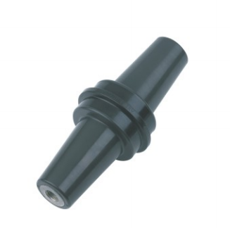
The distinction between main and auxiliary connections also makes future maintenance easier to understand. Two neighbouring transformer compartments can contain accessories with different operating conditions. We keep these differences explicit in our product application: a common enclosure colour, similar cable route, or shared heating function does not establish interchangeability between the connections inside.
Fitting New Electrical Equipment into an Existing Energy Centre
A heating retrofit often starts with available space rather than an empty site. A new transformer might be placed beside the boiler house while its incoming switchgear remains across a yard. The cable connection has to work at both ends of that route. We manufacture Separable Connector accessories for the defined equipment interfaces, while the installed arrangement must also accommodate the way the feeder enters each compartment.
A compact Separable Connector helps at the equipment connection, but the surrounding cable still occupies space. The bend below a transformer box, the support beside an RMU, and the route past a removable panel can determine whether the connection is convenient to assemble. We consider the final cable approach part of the application, especially when the equipment is placed against a wall or beside existing heating services.
In a retrofit, preserving the old cable route may be attractive because it avoids disturbing other plant areas. That does not automatically preserve the old connection assembly. A new transformer can have a different bushing, and a replacement cable can have different insulation dimensions even when its nominal conductor area looks familiar. Our Separable Connector configuration follows the equipment and cable that will actually be installed.
We also distinguish factory access from site access. A transformer or packaged station may be assembled in an open workshop, then installed with pipework or a fence close to its cable compartment. The connection remains usable only if the completed location leaves the access needed for the intended work. Assessing this early is particularly valuable at an energy centre where mechanical and electrical packages arrive at different times.
The same reasoning applies to removable plant equipment. A clear lifting route for a pump or heat exchanger can pass close to a cable enclosure. We prefer an arrangement in which those routine mechanical tasks do not require moving the MV cable. The Separable Connector stays at a defined equipment interface, while cable supports and the surrounding layout keep unrelated maintenance away from that connection.
Matching Existing Equipment and Replacement Cables
The equipment bushing is the first technical boundary. We manufacture different connection systems, and a 600A American-style deadbreak interface is not interchangeable with a 630A European-style interface merely because the current numbers are close. The same applies to a 200A loadbreak interface. For a heating plant, keeping the accessory family aligned with the equipment is more useful than comparing isolated catalogue ratings.
Cable fit supplies the other boundary. Conductor contact selection relates to the conductor, while the cable-side insulating fit depends on the actual cable insulation dimensions and construction. Nominal cross-section alone cannot establish a complete match. Our Separable Connector application therefore concerns the assembled cable interface, rather than a single size printed on the cable schedule.
In a heating upgrade, equipment changes can matter as much as the new load. If the project retains the existing transformer but changes its feeder cable, the equipment interface can remain unchanged while the cable-side parts require another configuration. If the transformer is replaced, both sides of the connection may need attention. A reusable trench does not settle either question.
For an auxiliary branch, our elbow range includes a 25kV-class, 200A version identified for the corresponding 24kV application. Its suitability follows that branch’s actual equipment and duty. The main heat pump supply needs its own appropriate connection arrangement.
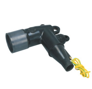
The connector’s operating duty must remain equally clear. Loadbreak capability applies only within the matched system’s rated conditions and prescribed procedures. Deadbreak accessories require the appropriate de-energized and isolated conditions for separation. Choosing a Separable Connector does not transfer the functions of the plant’s switches or protective devices into the cable accessory.
Keeping Connections Accessible through the Heating Season
Heating availability gives planned electrical maintenance a clear operational context. Work may be arranged around other available heat sources, expected demand, or a wider plant shutdown. The accessory cannot determine that operating plan, but its installed position can influence how readily the connection can be reached once the electrical conditions for work have been established.
We manufacture detachable Separable Connector accessories for appropriate equipment interfaces. Their value in a heat pump plant includes a defined point at which qualified personnel can carry out the intended connection work. That benefit is strongest when the enclosure opens fully and the cable does not need to be forced aside to reach another part. A separable structure alone does not guarantee a short outage.
Independent cable support is a practical part of this arrangement. A heavy feeder should approach the equipment without leaving its weight or persistent bending force on the connector body. Near a heating plant, the route also needs to remain separate from hot pipe surfaces and from areas where mechanical equipment is regularly handled. The final support arrangement belongs with the equipment and cable installation.
Our Separable Connector accessories operate within that completed installation. We do not rely on the rubber body to compensate for a poorly positioned clamp or an obstructed cable route. Keeping the connection physically settled makes its condition easier to assess and allows future work to focus on the intended interface rather than on recovering space around it.
A useful maintenance layout also avoids making one branch difficult to reach because another was installed first. For example, an auxiliary transformer connection may sit beside the main supply compartment. Leaving access to each compartment helps preserve their separate maintenance roles. It does not by itself create electrical independence; that comes from the plant’s switching and distribution arrangement.
Applying Sealed Accessories in a Working Heating Environment
The electrical room and the heating process area face different conditions. A room beside pumps or water treatment equipment can experience moisture, cleaning activity, or contamination that is absent from a protected switchgear room. Our Separable Connector application needs to reflect the actual enclosure location, rather than treating every position within an energy centre as the same environment.
We offer insulated and sealed cable accessory structures for their specified operating conditions. The connection surfaces still need the preparation and assembly required for the product. Sealing at an accessory interface does not make the complete transformer compartment resistant to every nearby leak, and it does not establish a protection rating for cable entries or the room itself.
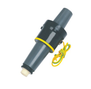
At a matching auxiliary connection, the equipment-side insert deserves the same attention as the elbow. Our 24kV, 200A single-pass casing joint is one equipment-interface component in the relevant range. Its fit depends on the specified equipment arrangement and mating accessory. We do not treat the elbow alone as a complete connection or assume that every nominally similar bushing accepts it.
The physical Connector interface is only one boundary in the installation. Drainage, ventilation, cable entry sealing, and separation from process equipment remain relevant around it. We keep the application of our accessories tied to their actual operating conditions, particularly where the electrical enclosure sits close to a water-based heating process.
For an outdoor transformer beside the plant, weather exposure and the enclosure arrangement can differ again. A product suitable within a defined installation still requires the appropriate equipment protection and cable entry arrangement. Our Separable Connector supplies its specified connection function; the completed location determines what other environmental measures are necessary.
Making the Connection Work as the Heating Plant Changes
An electrification project may begin with one heat pump and later add another heat source or transformer. We supply Separable Connector accessories for the selected distribution equipment. The useful approach is to give each new connection an appropriate physical position and defined accessory arrangement, without assuming that a spare connection point also represents spare electrical capacity.
For example, a future transformer position may be reserved beside the first unit while the initial feeder follows an existing wall. If that cable route occupies the future working space, a compact Separable Connector cannot recover the lost access. Keeping the next equipment position usable is an application decision that needs attention while the first connection is still being arranged.
Repeated equipment positions can use repeated accessory configurations where the interfaces and cables genuinely match. We manufacture the corresponding Separable Connector accessories within those defined systems. When another transformer or feeder differs, that difference needs to remain visible in the installed connection rather than being absorbed into a general assumption that all plant accessories are equivalent.
Our Separable Connector range supports the MV cable connection within this larger heating project. At YIEOU, we manufacture these assemblies and provide technical support for their application, with matching connection families and cable-side configurations suited to their equipment positions. The installed connection then remains accessible as the heating plant moves from commissioning into regular service.
Frequently Asked Questions
Where does a separable connection fit in a large heat pump installation?
Our Separable Connector accessories fit the specified MV cable interfaces at equipment such as transformers, RMUs, and cable branch enclosures supplying the installation. They are separate from the heat pump’s refrigerant circuit and low-voltage controls.
Does heat pump output determine the connector rating?
No. Thermal output does not directly establish the MV feeder duty or equipment interface. We apply the connection family and rating to the actual electrical equipment and cable serving that part of the plant.
Can the main supply and auxiliary transformer use different connection systems?
Yes, where their equipment and electrical duties require different arrangements. We offer distinct accessory families, and the complete connection at each branch must remain within its own specified interface system.
Can an existing feeder cable keep its old accessories after a retrofit?
That depends on the replacement equipment interface and the cable’s actual condition and dimensions. Our Separable Connector configuration follows the installed equipment and cable; retaining the route alone does not establish that the old assembly remains suitable.
Does a sealed accessory protect the entire electrical room from moisture?
No. The accessory provides its specified interface sealing when correctly assembled. Room conditions, equipment enclosure protection, and cable entry sealing still need to suit the heating plant location.
Can a deadbreak connection be separated while the plant is carrying load?
No. Deadbreak accessories require the appropriate de-energized and isolated conditions before separation. Load interruption belongs to suitable switching equipment; loadbreak accessories also have defined ratings and operating procedures.
What matters most when leaving space for another heat pump supply?
The reserved equipment position needs a usable cable route and access for connection work. An additional Separable Connector position does not establish spare feeder capacity or an independently switched circuit; those depend on the wider electrical arrangement.