
Compact substations in mines and heavy industrial plants often sit much closer to dust, moisture, vibration, cable trenches, mobile equipment, and changing production loads than a utility substation does. The medium-voltage cable connection may be enclosed, yet its working conditions are still shaped by the site. A Separable Connector has to match the equipment bushing and cable first, then fit the real compartment, cable route, maintenance practice, and environmental controls. Treating every T-shaped or elbow-shaped product as interchangeable can create a connection that is difficult to install, impossible to operate as intended, or unsuitable for the selected equipment interface.
Quick Answer
A Separable Connector for an industrial or mining compact substation should be selected from the actual connection point outward. Identify the bushing interface, voltage class, current class, and operating duty before choosing the Separable Connector body. Then match the conductor material, cable cross-section, diameter over insulation, screen construction, adapter, contact, grounding arrangement, and available installation space.
At YIEOU, we manufacture American-style and European-style medium-voltage cable accessories for defined interface systems. A 200A loadbreak elbow, a 600A deadbreak T-body, and a 630A European-style screened Separable Connector can all appear in compact distribution equipment, but they serve different interfaces and operating duties. The site name or substation type does not determine which system fits.
Start With the Connection Point Inside the Compact Substation
An industrial or mining site may use compact substations at a process building, crusher station, conveyor transfer point, pumping area, workshop, or underground distribution level. These locations do not all have the same electrical role. One unit may receive a main feeder and supply a transformer. Another may act as a switching point in a ring. A third may provide a branch connection for a remote load area. The cable accessory arrangement follows that role.
The equipment drawing is the best starting point because it identifies the physical bushing that the Separable Connector must mate with. A schedule that lists only 10kV, 15kV, or 24kV is incomplete. A useful schedule also shows the interface type, continuous current class, connector position, and any related bushing insert, rear interface, cap, junction, or test feature.
This matters when several equipment vendors supply one project. The primary switchgear, transformer cable box, RMU, and cable branch box may operate at the same nominal voltage while using different interface families. Standardizing the cable voltage across a mine does not automatically standardize every Separable Connector. The bushing drawing at each termination point remains the controlling reference.
Our Separable Connector range includes screened European-style front and rear arrangements for compatible equipment. We also manufacture American-style 200A and 600A accessory systems. Each family is selected around its own equipment interface rather than around a generic description such as “compact substation Separable Connector.”
Interface Family Comes Before the Current Number
Current ratings help define the connection system, but a nearby number does not prove interchangeability. A 600A American-style deadbreak Separable Connector and a 630A European-style Separable Connector usually belong to different bushing geometries, contact arrangements, product standards, and accessory families. The ten-ampere difference is not the main selection issue. The interface system is.
The same distinction applies between 200A loadbreak and higher-current deadbreak arrangements. A matched 200A loadbreak elbow may support loadbreak operation under the rated conditions of its complete system and the approved operating procedure. A 600A deadbreak Separable Connector does not perform the switching duty of the RMU or switchgear. It is disconnected only after the circuit has been properly isolated according to the installation procedure.
In industrial and mining substations, the Separable Connector position often indicates which questions matter. A main transformer feeder may use a higher-current T-body connection. A smaller radial circuit may use a 200A elbow system where the equipment was designed for it. A European-style RMU may use a 630A external-cone interface. These are examples of equipment arrangements, not rules based on load name alone.
Table 1. Interface Decisions for Compact Substation Cable Connections
| Connection factor | What it decides | Common mistake to avoid |
|---|---|---|
| Equipment bushing drawing | Connector family and mating geometry | Selecting from voltage and current labels alone |
| Rated current class | Compatible current path and accessory system | Treating 600A and 630A as interchangeable |
| Operating duty | Loadbreak or deadbreak handling | Using a deadbreak connector as a switching device |
| Connector position | Front, rear, elbow, cap, or related accessory | Assuming every rear position accepts any accessory |
| Applicable interface standard | Dimensional and electrical compatibility | Mixing American-style and European-style components |
Match the Product System to the Actual Feeder Role
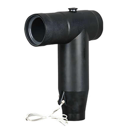
A product model becomes useful only after the equipment interface and feeder role are clear. For a European-style Type C connection, our QJT 12/24-630A front Separable Connector is designed for standard C-type bushings on switchgear, RMUs, transformers, and cable branch boxes. Its official product data lists a maximum system voltage of 24kV, a continuous current rating of 630A, copper or aluminum conductor compatibility, and conductor ranges of 25–500 mm² at 12kV and 25–400 mm² at 24kV. Those ranges narrow the product family; the final adapter still follows the actual insulation diameter.
An American-style 600A deadbreak connection belongs to another system. The JY TT-600 family provides a 15kV or 24kV class 600A cable termination for compatible apparatus, with configurations extending to large conductor cross-sections and an optional capacitive test point. It is relevant where the compact substation or transformer was built around the corresponding 600A deadbreak interface. Its T-shaped outline does not make it a substitute for the 630A European Separable Connector.
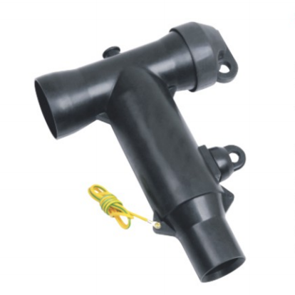
For a compatible 15kV 200A loadbreak system, the JY ZT-15/200 elbow Separable Connector is intended for underground cable connections to equipment fitted with the matching loadbreak interface. The product page identifies a 15kV, 200A rating, EPDM insulation, an optional capacitive test point, and cable conductor ranges that depend on the selected configuration. Its loadbreak function applies only within the matched system and rated procedure; it is not a general permission to disconnect any energized cable accessory.
These products illustrate why one mine or industrial plant can legitimately contain more than one Separable Connector family. The equipment interface, feeder rating, and operating method at each location decide the system. A site standard can reduce unnecessary variation, but it cannot erase genuine differences between the bushings supplied on unlike equipment packages.
Cable Construction Determines the Adapter and Contact
Once the Separable Connector family is known, the cable determines the cable-side components. Conductor cross-section is necessary, but it does not define the complete kit. Copper and aluminum conductors may require different contacts. Compacted and conventional stranded conductors can have different dimensions. Cables with the same square-millimeter value may also have different diameters over insulation.
That insulation diameter controls the fit of the cable adapter and stress-control interface. A loose fit can compromise sealing and the intended electric-field control. An excessively tight fit can prevent complete assembly or damage the prepared cable surface. The value should come from the actual cable datasheet or a controlled measurement on the cable that will be installed.
Screen construction also affects the preparation and grounding arrangement. Copper wire screens, tape screens, and other metallic screen designs need the correct restoration and earth connection. The Separable Connector body cannot compensate for damaged insulation, an irregular semiconductive cutback, an incorrect crimp, or a poorly supported grounding lead.
Mining and industrial projects often use more than one cable family across a site. A main incoming feeder, a transformer feeder, and a smaller branch circuit may share a nominal voltage while using different conductors and insulation dimensions. Assigning one adapter code to every cable because the cross-sections look similar can create a mismatch at installation.
Table 2. Cable Data Required for the Final Connector Kit
| Cable detail | Effect on the Separable Connector configuration |
|---|---|
| Voltage designation and maximum system voltage | Confirms the insulation class and compatible product family |
| Conductor material | Determines copper, aluminum, or bimetallic contact requirements |
| Conductor cross-section and construction | Narrows the contact size and crimping arrangement |
| Diameter over insulation | Selects the cable adapter and stress-control fit |
| Insulation material | Confirms compatibility with the specified product system |
| Metallic screen design | Changes cable preparation, screen continuity, and grounding details |
| Sheath and cable construction | Affects sealing, breakout, support, and installation method |
Dust Moisture and Contamination Change the Installation Controls
Compact substations may be enclosed, but mine dust, process dust, condensation, water from cleaning, and rapid temperature changes can still reach cable compartments. Environmental protection depends on the completed installation as well as the documented properties of the rubber body. The enclosure, cable entry, gland plate, connector interface, caps, grounding points, and drainage all contribute.
Product data must support any environmental claim used in the specification. For example, YIEOU lists fully screened and insulated constructions for the connector families described above, while specific product pages provide their own material and protection details. Those statements should not be copied from one model to another. A specified IP rating or temperature range applies only where the corresponding product documentation confirms it.
Clean assembly is especially important in dusty locations. Conductive particles, fibers, grease, and moisture left on the cable insulation or mating surface can reduce the quality of the interface. Cable preparation should take place under controlled conditions even when the substation itself is already installed in a harsh area. Protective covers remain in place until assembly, and unused interfaces require the correctly rated cap from the same system.
The ordinary meaning of a Connector is a mating electrical interface. At medium voltage, the connection also includes stress control, insulation, shielding, sealing, and grounding. This is why a visually clean outer surface does not prove that the internal interface is correctly matched or free from contamination.
Where equipment is installed in a classified hazardous area, the required approval for that location has to be established separately for the complete equipment package. A weather-resistant or sealed cable accessory description does not by itself establish hazardous-area suitability.
Compartment Space and Cable Support Need One Drawing
Industrial and mining cables can be heavy, stiff, and routed through trenches or from below a compact enclosure. The Separable Connector should meet the bushing without carrying the cable’s weight or being forced sideways by the bend. The installation drawing therefore needs to show the connector body and the cable route together.
The relevant envelope includes the bushing, connector body, adapter, rear accessory or cap, grounding lead, cable bend, gland plate, cleats, neighboring phases, and access needed for assembly. A connector can fit the bushing while the cable still collides with a wall or exceeds its practical bend space. Rear connectors and stacked accessories add depth and may move a second cable into a restricted zone.
Cable support is part of interface reliability. Vertical cables need cleats or supports that prevent their weight from pulling on the contact. Horizontal routes need support close enough to control movement without imposing a sharp bend at the stress-control area. Mechanical vibration from nearby crushers, pumps, conveyors, or ventilation equipment should be addressed through the substation and cable-support design rather than by expecting the connector body to absorb repeated movement.
Installation access also matters. The team needs room to prepare the cable, crimp the contact, apply the adapter, seat the Separable Connector, complete grounding, and inspect the final position. The cable should not be twisted to make the connector line up with a poorly oriented bushing. Correcting the bushing orientation or cable route on the drawing is safer than forcing the assembled interface on site.
Maintenance and Spares Must Preserve Interface Identity
A mine or industrial plant may have many compact substations installed at different dates. The cable compartments can look similar while containing different connector systems. Clear identification prevents a 600A American-style spare, a 630A European-style spare, or a 200A loadbreak component from being issued to the wrong job.
The asset record should identify the equipment bushing, voltage class, current class, Separable Connector model, adapter code, conductor contact, cable designation, and related cap or rear accessory. A generic description such as “MV T-connector” is not enough for spares. It hides the exact interface relationship that was verified during selection.
Condition inspections can include connector seating, external screen grounding, cable support, contamination, mechanical damage, abnormal heating, and visible discharge marks. These observations indicate whether further investigation is needed. They do not authorize live manipulation of a deadbreak connection or replacement with a part from another interface family.
Where a capacitive test point is provided, its intended instrument and procedure should be recorded with the product. A test point may support voltage indication, phase comparison, or a compatible fault indicator depending on the design. It does not change a deadbreak connector into a loadbreak device or replace the isolation procedure for cable work.
Our second Separable Connector product family link covers 600A cable accessories for high-current medium-voltage distribution. Keeping that family separate from European 630A and 200A loadbreak systems makes model records, replacement stock, and maintenance instructions more precise.
Build a Repeatable Connection Package for Each Substation Type
Repeatability is valuable when several compact substations serve similar production areas. The repeatable item should be a complete connection package tied to one verified equipment and cable combination. It includes the bushing interface, connector body, adapter, conductor contact, grounding components, caps or rear accessories, and the installed cable route.
A package can be repeated across truly identical substations, but a new equipment vendor or cable type requires the interface and cable data to be checked again. This approach controls variation without assuming that every location in the plant uses the same connector. It also keeps purchasing descriptions tied to technical reality instead of a broad product nickname.
YIEOU manufactures 200A loadbreak, 600A deadbreak, and European-style screened cable accessory families for different medium-voltage equipment interfaces. In industrial and mining projects, the useful manufacturing contribution is a consistent product family with defined mating components, cable ranges, and accessory positions. The final selection still follows the actual bushing, cable, duty, and compartment at each connection point.
The correct Separable Connector is therefore the one that fits the complete connection. Site conditions influence sealing, cleanliness, support, access, and inspection, but they do not replace the basic interface decision. Starting with the equipment bushing and finishing with the installed cable route produces a specification that can be manufactured, installed, identified, and maintained without mixing unlike systems.
Frequently Asked Questions
Which Separable Connector is suitable for a mining compact substation?
The suitable connector depends on the equipment bushing, voltage class, current class, operating duty, cable construction, and compartment layout. The application name alone cannot determine whether the connection should use a 200A loadbreak, 600A deadbreak, or 630A European-style system.
Can a 600A deadbreak connector replace a 630A European connector?
No. Their current ratings are close, but the equipment interface, contact arrangement, applicable standards, and compatible accessories can differ. Selection follows the actual bushing system.
Is a 200A loadbreak elbow suitable for every compact substation feeder?
No. It is suitable only where the current duty and matching loadbreak interface support that product system. Higher-current or differently standardized interfaces require their own connector family.
Does cable cross-section determine the adapter size?
It narrows the options but does not finish the selection. Diameter over insulation, conductor material and construction, voltage class, insulation type, and screen design also affect the final kit.
How should heavy mining cable be supported near the connector?
Cable cleats and supports should carry the cable weight and control the bend before it reaches the connector. The connector body should align with the bushing without supporting the cable or being forced sideways.
Does a sealed connector automatically suit a hazardous area?
No. Environmental sealing and hazardous-area approval are different requirements. Suitability for a classified location must be confirmed for the complete equipment and accessory package.
What should a spare-parts record contain?
It should identify the interface family, voltage and current class, connector model, adapter code, conductor contact, cable designation, and compatible caps or rear accessories. This prevents visually similar but incompatible parts from being issued together.