
A berth can gain a new shore power cabinet while the electrical connection feeding it remains hidden inside a substation several buildings away. That fixed cable connection matters whenever another berth comes into service, equipment is replaced, or an outage has to fit around vessel movements. The useful question is how the shore-side medium voltage cable meets the equipment and remains accessible over the life of the installation. At YIEOU, we manufacture separable cable accessories for those equipment interfaces. Our focus is the screened connection inside compatible distribution equipment, with the application shaping the cable arrangement, protection, and space around it.
Quick Answer
A Separable Connector can serve the fixed medium voltage connection feeding shore power equipment where the equipment bushing, cable, and connector system are compatible. We offer screened front connectors and related accessories for connections in ring main units, cable branch boxes, and prefabricated substations. In a port, their value lies in an organized equipment interface that can accommodate appropriate cable configurations and planned maintenance.
The shore power application does not determine the connector family by itself. We base the connection on the actual shore-side equipment interface and its electrical duty. The removable marine coupling handled between the quay and a vessel is a separate application. Our Separable Connector discussion here concerns installed distribution cables within the port power network.
Shore Power Puts More Attention on Fixed Cable Connections
Shore power brings an additional reason to revisit the connection between an existing port feeder and new electrical equipment. A project may introduce a dedicated substation, add a distribution enclosure near a berth, or extend an established cable route. Each arrangement places the cable interface in a different working environment. We manufacture our cable accessories for the equipment connection at those locations, so the enclosure and cable route matter as much as the name of the terminal being served.
The installation also has a life beyond the first energized berth. Port areas change as operating patterns, vessel services, and equipment locations develop. A connection that looks convenient during initial assembly may become difficult to reach after surrounding cables and cabinets are in place. Our Separable Connector assemblies provide a defined interface at compatible equipment; keeping that interface useful requires room for its actual installed configuration.
Consider a shore power equipment room connected to an existing port distribution building. The feeder may arrive from a trench while the cable compartment sits above floor level. We would use a suitable Separable Connector configuration at the equipment interface, with the cable supported along its route. That arrangement makes the boundary between the fixed cable and the equipment clear. It also avoids treating the final connection as a small detail left after the cabinet position has already been fixed.
For switchgear manufacturers and substation builders, this is where our product range fits naturally. We supply Separable Connector accessories that connect compatible insulated cables to the distribution equipment. The shore power converter, vessel controls, and berth operating system retain their own functions. A well arranged Separable Connector supports the fixed electrical connection without taking over those wider responsibilities.
Phased Berth Expansion Needs Usable Connection Space
A port may bring one berth into service before extending shore power to neighboring berths. During that first stage, an unused cable position can seem unimportant. Later, the same position may become the practical route for an additional feeder. We offer front and corresponding rear Separable Connector arrangements within our European cable accessory range, allowing suitable equipment configurations to accommodate more than one cable connection where the complete assembly permits it.
The value of that option depends on how the first stage occupies the compartment. If the original cable crosses the future connection position, adding a second cable becomes a rearrangement of existing work. A Separable Connector arrangement is more useful when each installed cable has a route and support position that leaves the intended extension accessible. Expansion then starts from a connection layout that already recognizes the next stage.
For a future cable position, we also manufacture insulating caps for corresponding interfaces. Our JYM-K cap range includes versions identified for 12kV and 24kV equipment connections. A compatible rated cap provides the intended insulating enclosure at an unused bushing; a temporary shipping cover has a different purpose. The cap, its grounding provision, and the equipment interface form part of the installed arrangement.
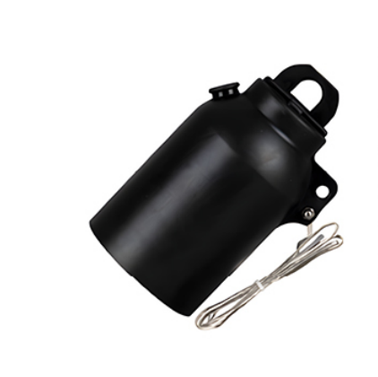
That detail has a practical consequence during staged construction. A spare connection can remain clearly identifiable and protected while nearby cable routes are still changing. When the next stage proceeds, the team has a defined equipment position rather than an improvised opening. Our Separable Connector accessories support that continuity, provided the spare position and its protection suit the actual equipment.
Adding a Separable Connector does not increase the capacity of the existing feeder or bushing. A rear connection also does not create an independent switched circuit. The switchgear and circuit design determine how the additional cable is used.
The Equipment Interface Sets the Product Direction
We manufacture different cable accessory families for different equipment interfaces. A Separable Connector cannot be chosen simply because its current rating resembles that of another. The bushing system establishes the product direction before the cable configuration is completed.
In a port extension built around compatible European-style equipment, we offer a front connection that brings the fixed feeder into the cable compartment at the bushing. The accessory forms a defined cable-to-equipment connection within that installation. The advantage is practical: the termination position remains identifiable when adjacent equipment is later added, while the equipment interface still determines which front connection belongs there.
Cable fit remains part of the connection. The conductor contact suits the conductor, while the cable adapter must suit the diameter over insulation. Two cables carrying the same cross-sectional designation can have different insulation dimensions. We manufacture the Separable Connector as an assembly of compatible parts, so choosing a cable size alone does not settle the complete configuration.
Our Separable Connector range is relevant where these interface and cable conditions align. In practical terms, that means the connection follows the installed equipment rather than a generic preference for a particular shape. It also means an extension at one berth need not repeat the connector used elsewhere in the port if the equipment interface differs.
The distinction becomes especially useful when an older feeder remains in place and a new distribution enclosure is added nearby. The existing cable route may be reusable, while the new equipment introduces a different connection arrangement. We retain the cable and equipment requirements as separate parts of product matching. That keeps a familiar-looking cable from becoming the sole reason for carrying an unsuitable accessory into the new installation.
Compact Enclosures Still Need Room Around the Connection
A shore-side substation may have limited floor space, particularly when the project sits among existing port buildings and traffic routes. A compact Separable Connector helps form an organized connection within suitable equipment. We offer front connector structures for this purpose, but the connector body is only one part of the occupied space. The completed cable route also needs room below and beside it.
Our Separable Connector layout therefore follows the cable entry direction as well as the bushing position. With a bottom cable entry, a natural upward route can leave the connection visible from the compartment door. A crowded crossing arrangement may hide the grounding lead or place another cable directly in front of the working position. These differences affect how the installation can be inspected after construction is finished.
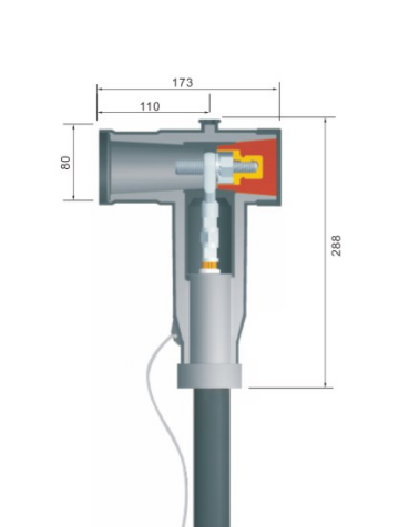
The space needed during assembly also deserves attention. The enclosure may be open and easily accessible at the workshop, then become surrounded by adjacent equipment on site. A connection that can be assembled from the side in the factory may later be reachable only from the front. We favor an installed arrangement in which the same cable interface remains accessible in its final setting.
Cable support contributes to that arrangement. A heavy feeder entering from a trench needs support that carries its weight independently of the connector. The cable can then approach the bushing without using the connection body as a lever or hanging point. Our Separable Connector provides the electrical interface; the cable support keeps the mechanical load in the intended part of the installation.
A practical example is a berth extension installed beside an existing cable cabinet. Leaving the new cable close to the wall may keep the doorway clear, but a tight turn at the connector can make future access awkward. A slightly different entry route can preserve a more usable connection position without changing the product family. The improvement comes from arranging our accessory and the cable together, rather than judging compactness by the body dimensions alone.
Coastal Conditions Shape the Installed Arrangement
A port location brings attention to moisture, airborne contamination, and the condition of the enclosure surrounding the cable connection. We manufacture screened, sealed Separable Connector structures for the applications stated in our product range. Their installed performance depends on correct assembly and appropriate operating conditions. A Separable Connector inside a protected electrical room faces a different exposure from one in an enclosure close to an open quay.
The location within the port is therefore useful application information. Doors opened during construction can expose a cable compartment to dust and moisture even if the finished room is protected. We keep the mating surfaces protected until assembly and use the specified cable preparation and installation method. Clean connection surfaces and correct seating support the intended insulation and sealing function.
Our published front connector conditions also distinguish normal use from severe pollution, salt spray, and chemically corrosive environments requiring special consideration. We do not turn general outdoor suitability into an unrestricted marine claim. The practical product question is whether the selected assembly and enclosure suit the actual exposure at that connection.
The same reasoning applies to water around cable entries. The cable accessory seals its intended interfaces; the enclosure still needs its own suitable treatment of entries and environmental exposure. We describe our Separable Connector as part of that installed arrangement. It cannot compensate for a cabinet location or water path that puts the complete assembly outside its intended conditions.
This approach leaves room for useful choices without filling the project with unnecessary accessories. An indoor distribution room may place greater emphasis on orderly cable access, while an outdoor berth-side enclosure places more emphasis on protection during assembly and subsequent access. We use the same product principles in both cases, with the installation conditions determining which details become most significant.
Protection Accessories Belong Where the Circuit Needs Them
A port feeder can pass through several pieces of equipment before reaching the shore power installation. Protection at one location does not automatically describe what is fitted at another. We manufacture rear-connected surge arresters for corresponding cable accessory systems, so protection can be integrated at a suitable cable interface when the circuit requires that arrangement.
For a matching 10kV distribution application, our HBLQ-17/50 rear-connected arrester is one such option. Its role is to limit lightning and switching overvoltage at the intended connection. The arrester has its own system and operating requirements; the presence of a Separable Connector does not by itself establish which arrester is suitable.
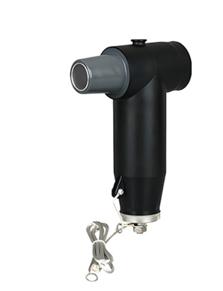
That is a useful distinction during a berth expansion. An enclosure may have room for another cable, yet little space left for a protection accessory and its grounding route. We offer the corresponding accessory as part of an appropriate connection system. Its installed position still has to remain accessible, with the surrounding cables arranged around the complete assembly.
A Connector and a surge arrester perform different duties. We integrate the necessary connection and protection accessories through their corresponding interfaces, following the circuit requirements.
For our products, the useful outcome is a connection arrangement with the necessary functions present and identifiable. A protected spare interface, an additional cable connection, and an arrester are different configurations serving different needs. We retain that distinction as the port develops, so an accessory earns its place through the application rather than through a longer equipment list.
Planned Outages Give Separable Connections Their Practical Value
Port operations can make access to electrical equipment a scheduling issue as well as a physical one. A cable connection may need attention between operating periods or during a larger equipment change. We manufacture Separable Connector accessories that provide a defined interface for suitable maintenance work. Their practical value becomes clearer when the installed connection can be reached without first moving unrelated cables.
A deadbreak Separable Connector is disconnected only under the required de-energized and isolated conditions. Switching and electrical isolation belong to the appropriate equipment and operating procedure. The separable structure supports access to the cable interface after those conditions are established; it does not turn the cable connector into a load switch.
Within that boundary, the arrangement can support replacement of compatible equipment or work on an individual cable connection. The useful feature is a defined point at which the cable accessory and equipment meet. We do not promise that every disconnected part can be reused or that every maintenance task avoids further cable work. The product condition and applicable installation instructions govern the actual work.
For a staged shore power installation, clear access also helps preserve the original intent of the connection. A capped spare position remains identifiable, a grounding lead remains visible, and an additional cable does not cover the original working position. Those details make our Separable Connector configuration easier to understand when the compartment is reopened months or years after initial construction.
We offer our Separable Connector range for compatible shore-side distribution equipment with this complete installation in mind. At YIEOU, we manufacture the front connections and related cable accessories that form those equipment interfaces. For port shore power, the strongest arrangement combines an appropriate product configuration with a cable route, enclosure, and service position that remain usable as the berth develops.
Frequently Asked Questions
Where does a Separable Connector fit in a shore power installation?
It can connect a fixed medium voltage feeder to compatible shore-side distribution equipment. Our Separable Connector applications include equipment cable interfaces in ring main units, cable branch boxes, and prefabricated substations.
Is this the coupling connected to the vessel?
The fixed equipment connection discussed here serves the port distribution network. A removable ship-to-shore coupling has different handling and application requirements, so its selection is a separate task.
Does every shore power berth use the same connector rating?
No. The actual distribution equipment and circuit duty determine the appropriate connection. We manufacture different accessory families because one connector rating or shape cannot cover every equipment interface.
Can a future berth connection remain unused during the first stage?
A suitable spare equipment interface can be protected with its corresponding rated insulating cap. Our cap range includes products for matching 12kV and 24kV interfaces; the complete installed arrangement must suit the equipment.
Does a sealed Separable Connector make the whole cabinet waterproof?
The accessory seals its intended connection interfaces under its specified conditions. Cable entries, enclosure protection, drainage provisions where applicable, and the surrounding installation retain their own requirements.
Is a surge arrester necessary simply because the installation is at a port?
Its use follows the circuit protection requirements and the compatible accessory system. We offer corresponding rear-connected arresters for specified applications, rather than treating the coastal location as sufficient reason to fit one.
Can the connection be separated while shore power is supplying a vessel?
A deadbreak connection requires the prescribed de-energized and isolated conditions before separation. The appropriate switching equipment and operating procedures establish those conditions.