
Introduction
Medium-voltage cable systems are expected to operate safely and continuously for many years. However, the long-term reliability of these systems does not depend only on the quality of the cable, transformer or switchgear. The condition of each cable connection point is equally important.
A cable may have the correct conductor size, insulation level and current-carrying capacity, but the system can still develop faults when the interface between the cable and the equipment is poorly selected or installed. Loose contact, incorrect cable preparation, moisture ingress, concentrated electric stress and mismatched components can gradually weaken the connection.
These problems do not always cause an immediate shutdown. In many cases, they begin with a small increase in contact resistance, an abnormal temperature difference or a minor insulation defect. Over time, the condition may develop into overheating, partial discharge, surface tracking or complete insulation failure.
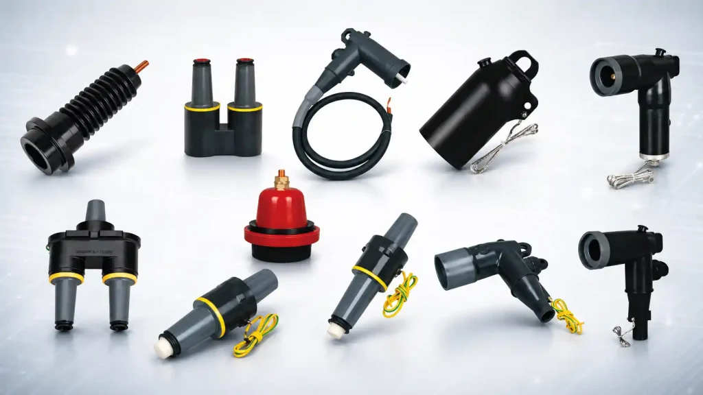
A Separable Connector creates a removable, screened and insulated interface between a medium-voltage cable and equipment such as a transformer, ring main unit, switchgear panel, compact substation or cable branch box. It allows the cable to remain securely connected while still being accessible for inspection, testing, replacement and system modification.
Unlike a simple mechanical joint, a Separable Connector must perform several functions at the same time. It must carry current, control the electric field, maintain insulation, provide mechanical stability and protect the cable interface from environmental exposure.
Reliable operation therefore depends on more than choosing a product with the correct voltage printed on its label. The cable conductor, insulation diameter, equipment bushing, contact component, stress-control structure, grounding arrangement and sealing system must all work together.
When a Separable Connector and the surrounding Medium Voltage Cable Accessories are correctly coordinated, the complete cable interface becomes more reliable, easier to maintain and more adaptable to future network changes.
What Cable Connection Problems Can a Separable Connector Help Prevent?
Cable connection faults usually develop because electrical, mechanical or environmental conditions at the interface are not properly controlled. A correctly selected Separable Connector helps reduce these risks by creating a defined connection structure between the cable and the equipment.
Poor contact and abnormal temperature rise
One of the most common problems at a medium-voltage cable interface is excessive contact resistance.
Current must pass from the cable conductor through the contact component and into the equipment bushing. If the conductor has been prepared incorrectly, the contact is poorly crimped or the connector is not fully inserted, the electrical resistance at the interface can increase.
Even a relatively small increase in resistance can generate additional heat under continuous load. This heat may accelerate oxidation, weaken the contact surface and damage nearby insulation. As the contact deteriorates, the resistance can rise further, creating a repeating cycle of overheating and material degradation.
A Separable Connector uses a defined contact system designed for a specified conductor range and rated current. When the correct contact is installed with approved tools, it helps maintain stable mechanical pressure and electrical continuity.
The connector itself, however, cannot correct poor workmanship. Incorrect crimping, conductor contamination or damaged strands can still lead to an unreliable interface.
Concentrated electric stress
The electric field inside a medium-voltage cable is controlled by its insulation and semiconductor layers. During cable termination, these layers must be removed and reshaped so that the conductor can connect to the equipment.
This change in cable geometry creates a transition point where electric stress can become concentrated. If the transition is not controlled, it may contribute to partial discharge, insulation erosion and premature failure.
A Separable Connector normally includes a stress-control structure that manages this transition. Its conductive and insulating layers help distribute the electric field more evenly around the cable end.
For this structure to work correctly, the connector must match the actual cable insulation diameter. A connector that is too loose or too tight may not provide the intended stress-control performance.
Moisture and contamination
Medium-voltage connections can be exposed to humidity, condensation, dust, salt, industrial contamination and occasional water ingress. These conditions are particularly important in outdoor substations, cable chambers, compact equipment rooms and installations with large temperature variations.
A properly assembled Separable Connector forms an enclosed interface around the cable termination. This helps reduce the risk of moisture or contamination entering critical insulation and contact areas.
The quality of the seal depends heavily on surface preparation. Dirt, grease, fibres, metal particles and damaged insulation can all affect the interface. The connector body, cable insulation and equipment bushing must therefore be cleaned and inspected before assembly.
Unsafe exposed interfaces
Unused or poorly protected bushings can create a safety risk and may also become contaminated over time.
A screened Separable Connector encloses the energized connection within an insulated body. Many designs also include a conductive outer screen that can be connected to earth, helping maintain a controlled external surface potential.
This structure reduces the likelihood of accidental contact with live internal parts during normal operation. It also allows the connector to be used in compact equipment where space is limited.
The screened design does not make the connector safe to handle while energized. Isolation, voltage verification, grounding and approved operating procedures are still required.
Incompatible connection components
A connector may appear suitable because it has the correct voltage and current rating, yet still be incompatible with the equipment bushing.
Medium-voltage interfaces are based on specific mechanical dimensions and electrical characteristics. An incompatible Separable Connector may not fully engage with the equipment interface, even when the assembly appears visually complete.
This can result in unstable contact pressure, increased resistance or reduced dielectric strength. Before installation, the equipment bushing type, current class, interface standard and connector family must all be confirmed.
Table 1: Common Cable Connection Problems and Preventive Measures
| Cable connection problem | Possible cause | How the connector system helps | Additional action required |
| Excessive temperature rise | Loose contact, poor crimping or overload | Provides a defined contact structure | Verify conductor preparation and operating current |
| Partial discharge | Electric stress concentration or insulation damage | Controls the electric field around the cable end | Match the connector to the cable insulation diameter |
| Moisture ingress | Poor sealing or contaminated surfaces | Creates an enclosed cable interface | Clean and inspect all mating surfaces |
| Intermittent connection | Incomplete insertion or incompatible parts | Uses a standardized equipment interface | Confirm full engagement and component compatibility |
| Surface tracking | Dust, moisture or damaged insulation | Screens and insulates the energized interface | Maintain clean surfaces and replace damaged parts |
| Exposed spare bushing | Missing protective accessory | Allows the use of an insulation cap | Fit a correctly rated and compatible cap |
| Surge-related damage | Lightning or switching overvoltage | Can be coordinated with a surge arrester | Confirm the network protection design |
A Separable Connector therefore helps prevent cable problems by controlling several conditions at the same time. It provides much more than a physical link between two conductive components.
How Does a Separable Connector Create a More Reliable Cable Interface?
The reliability of a cable connection depends on how effectively it manages current flow, insulation, mechanical force, electric stress and environmental exposure.
A Separable Connector combines these functions in one compact assembly. Each internal layer and component has a specific role in maintaining the stability of the connection.
The conductor contact carries the current
The conductor contact transfers current from the cable into the equipment bushing.
It must match the conductor material, structure and cross-sectional area. Copper and aluminium conductors may require different preparation methods, and compacted conductors may have different dimensions from conventional stranded conductors.
If the contact is too large, the crimp may not provide sufficient compression. If it is too small, the conductor may be damaged or may not enter the contact correctly.
The rated current of a Separable Connector depends on the complete current path. A suitable connector body cannot compensate for an incorrectly selected or poorly installed contact.
The insulation body protects the live connection
The main insulation body separates the energized contact from the surrounding environment.
Its material and thickness are selected to withstand the rated system voltage and associated electrical stress. The internal surface must also fit closely around the cable insulation and equipment interface.
Air gaps, scratches and contamination can reduce dielectric performance. The connector body should never be forced onto a cable that falls outside the specified diameter range.
A loose fit may reduce sealing and stress control, while an excessively tight fit may damage the insulation or prevent full assembly.
The stress-control layer manages the electric field
The end of the cable semiconductor layer is one of the most electrically sensitive areas of a termination.
A Separable Connector uses conductive or semiconductive structures to control the transition between the cable screen and the energized conductor. This helps prevent the electric field from concentrating at a sharp edge.
Accurate cable preparation is essential. If the semiconductor cutback is too short, too long or irregular, the stress-control structure may not align with the intended position.
Smooth surfaces and correct dimensions are therefore critical to reliable insulation performance.
The conductive screen supports grounding
Many screened connectors have a conductive outer layer that is connected to earth.
This layer helps maintain a controlled surface potential around the assembled Separable Connector. It also supports a fully screened connection arrangement inside compact equipment.
The outer screen must be connected correctly to the cable screen and grounding system. A loose or damaged earth lead can reduce the intended protective function.
The equipment interface provides alignment
The connector must fit accurately onto the equipment bushing or bushing insert.
This interface provides both mechanical alignment and electrical contact. If the connector does not reach its intended final position, contact resistance and dielectric stress can increase.
For a 200A system, the Separable Connector may be installed on a compatible loadbreak bushing insert, casing seat or junction. Each component must belong to the correct interface family.
Parts with similar shapes or ratings should not automatically be treated as interchangeable.
Loadbreak and deadbreak designs serve different purposes
Some connector systems are designed for specified loadbreak operations, while others must only be disconnected after the circuit has been isolated.
A loadbreak Separable Connector contains structures intended to control the switching process under defined operating conditions. This does not mean that it can be disconnected without training, approved tools or a verified procedure.
A deadbreak or non-loadbreak connector must not be operated while carrying load current.
The operating method should be confirmed during system design and clearly understood by the personnel responsible for maintenance.
A complete connection depends on coordinated accessories
The connector body is only one part of the system.
A complete installation may also include a bushing insert, junction, grounding elbow, insulation cap, casing connector or surge arrester. These Medium Voltage Cable Accessories must be electrically and mechanically compatible with the selected Separable Connector.
System reliability depends on how well all of these components work together.
Why Can a Separable Connector Make Installation and Maintenance Easier?
A permanent cable termination may provide reliable service, but it can be difficult to remove when equipment needs to be replaced, tested or extended.
A Separable Connector creates a detachable cable interface. This can make original installation more organized and future maintenance more manageable.
Standardized equipment connection
Transformers, ring main units, switchgear and compact substations often use defined bushing interfaces.
A compatible Separable Connector can be assembled onto the cable and connected directly to the equipment. This reduces the need for a large exposed termination inside the cabinet.
The modular design is particularly useful in equipment with limited internal space. It can also help installers follow a more consistent connection procedure across similar projects.
Cable preparation still requires accuracy. The conductor, insulation, semiconductor layer and outer sheath must all be cut to the correct dimensions.
Easier cable replacement
When a cable is damaged, a detachable connection can make it easier to separate the cable from the equipment.
The equipment bushing may remain in place while the cable and Separable Connector are removed. This can reduce the amount of equipment disassembly required during repair work.
The same connector should not automatically be reused. Its condition, product design and maintenance requirements must be reviewed before reinstallation.
More convenient testing
Certain connector designs include a capacitive test point. When used with suitable equipment, this may support voltage indication or phase identification.
A Separable Connector may also provide easier access for cable testing after the circuit has been isolated and the connection has been safely disconnected.
Testing requirements should be considered before the system is installed. Some procedures may require adapters or additional Medium Voltage Cable Accessories.
The test method and voltage must be suitable for both the cable insulation and the connected equipment.
Support for future network extension
Distribution systems often need to change when new loads, transformers or feeder circuits are added.
Junctions, pass-through components and modular connection arrangements can create additional cable interfaces without requiring complete replacement of the main equipment.
A Separable Connector system can therefore support future network modification more efficiently than a fixed connection arrangement.
However, the availability of a physical connection point does not confirm that the system can carry additional load. Current capacity, protection coordination, fault level and transformer loading must still be reviewed.
More controlled maintenance preparation
Grounding elbows and insulation caps can support a more organized maintenance procedure.
After a circuit has been isolated, tested and confirmed de-energized, a compatible grounding elbow may be installed in accordance with the approved safety procedure.
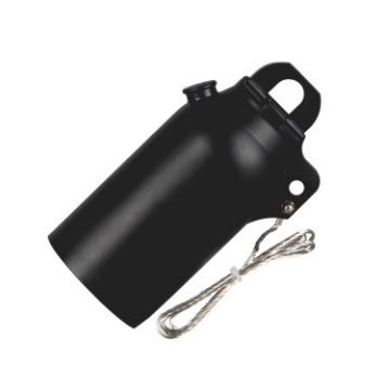
Unused equipment interfaces should be protected with correctly rated insulation caps. This helps maintain insulation, prevent contamination and clearly identify spare connection points.
These accessories help establish defined conditions for operating, grounded and unused interfaces.
Reduced disruption during planned work
The removable structure of a Separable Connector can reduce the amount of mechanical work required during planned maintenance.
Technicians can access the cable interface without rebuilding a complete permanent termination. This may shorten maintenance activities and make future replacement more predictable.
The benefit depends on equipment layout. Sufficient clearance, suitable cable routing and correct cable support are still required.
A connector installed in an overcrowded cabinet may remain difficult to remove, even when the connection itself is separable.
What Should Be Checked Before Choosing a Separable Connector?
Connector selection should begin with the cable and equipment data, not with product appearance or price.
A Separable Connector must match the electrical ratings, physical dimensions, operating method and environmental conditions of the complete system.
System voltage and insulation level
The connector must be suitable for the rated system voltage, maximum operating voltage and required insulation level.
Systems described as 15kV, 17kV or 24kV may have different insulation coordination requirements. The selected connector, bushing and related accessories should therefore be checked against the full equipment specification.
Choosing a component with a higher printed voltage does not automatically confirm compatibility. Interface design and insulation characteristics must also match.
Rated current and load profile
A common American-style connection system may use a 200A interface.
The current rating should be reviewed against the continuous operating load, temporary loading conditions and future expansion. Ambient temperature, cable size and equipment design can also affect thermal performance.
A 200A Separable Connector should not be treated as an isolated current-carrying component. The cable, contact, bushing and junction must all support the same current path.
Conductor material and size
The connector contact must fit the actual conductor.
Selection should consider conductor material, cross-sectional area, strand structure and compaction. Copper and aluminium conductors may require different contact designs or preparation methods.
The wrong contact can lead to incomplete crimping, excessive deformation or unreliable electrical pressure.
Actual insulation diameter
Nominal cable size alone is not sufficient for connector selection.
Two cables with the same conductor area may have different insulation diameters. A Separable Connector must fit the actual measured diameter to provide correct sealing and stress control.
Cable manufacturing tolerances and insulation designs can create important dimensional differences. The insulation diameter should therefore be measured before ordering the connector.
Equipment bushing type
The equipment interface must be identified accurately.
A 200A loadbreak bushing is different from a higher-current deadbreak interface. The connector, bushing insert, casing seat and junction must all belong to compatible interface categories.
Equipment drawings, markings and technical documentation should be checked before procurement. Visual similarity is not a reliable selection method.
Required operating method
The intended operating procedure also affects connector choice.
If the system requires specified loadbreak operation, both the connector and the equipment interface must be designed for that purpose.
Where disconnection will only take place after isolation, a non-loadbreak arrangement may be suitable.
The operating team should understand the distinction before the system is energized.
Environmental conditions
Temperature, humidity, dust, pollution, altitude, salt exposure and water ingress can influence long-term connector performance.
Outdoor systems may require greater attention to sealing and mechanical support. Indoor installations can still experience condensation where equipment temperature changes rapidly.
The selected Separable Connector should be suitable for the actual installation environment rather than ideal laboratory conditions.
Cable routing and mechanical support
Cable weight and bending force should not pull the connector away from the equipment bushing.
Heavy cables may require clamps or additional support. The cable route should also allow the connector to be installed and removed without exceeding the minimum bending radius.
Adequate operating clearance should be considered during the cabinet design stage.
Table 2: Separable Connector Selection Checklist
| Selection factor | Information to confirm | Why it matters |
| System voltage | Rated voltage and maximum operating voltage | Confirms dielectric suitability |
| Rated current | Continuous load and expected future demand | Helps prevent thermal overload |
| Cable conductor | Material, construction and cross-sectional area | Determines contact and crimping requirements |
| Insulation diameter | Actual measured insulation diameter | Ensures correct sealing and stress control |
| Equipment interface | Bushing type and dimensional standard | Prevents incomplete or incompatible assembly |
| Operating method | Loadbreak or de-energized disconnection | Determines the correct connector category |
| Installation environment | Indoor, outdoor, humidity, pollution and altitude | Affects sealing and material performance |
| Cable layout | Bending radius, support and cabinet space | Reduces mechanical stress |
| Testing requirements | Voltage indication and cable test method | Identifies the need for test points or adapters |
| Related accessories | Junctions, caps, grounding elbows and arresters | Ensures complete system coordination |
Completing this review before installation helps prevent rework, material waste and project delays.
How Should a Separable Connector Be Installed and Inspected?
Even a correctly selected connector can fail when the cable is prepared or assembled incorrectly.
Installation should follow the instructions for the specific Separable Connector. General experience should not replace product-specific dimensions, tooling and procedures.
Verify the components before cutting the cable
Before cable preparation begins, the installer should confirm the voltage class, rated current, conductor range, insulation diameter and equipment interface.
The connector body, contact and accessories should be checked for damage or contamination. The equipment bushing should also be inspected.
A scratched or contaminated bushing may compromise the connection even when the Separable Connector is new.
Prepare the cable accurately
Cable preparation has a direct effect on electrical performance.
The outer sheath, metallic screen, semiconductor layer and insulation must be removed according to the specified dimensions. Cuts should be smooth and controlled.
The cable insulation should not contain deep scratches, and the semiconductor edge should not be rough or uneven.
Sharp marks can create local electric stress. The prepared surface should therefore be smooth, clean and free from conductive particles.
Crimp the contact with the correct tooling
The conductor contact should be installed with the specified crimping tool, die and sequence.
An incorrect die may produce a crimp that appears secure but does not provide the required compression. The contact orientation should also be checked before crimping.
Once the contact has been compressed, changing its position may require replacement.
Clean and lubricate the interface correctly
The cable insulation and connector surfaces must be cleaned with approved materials.
Dust, grease, fibres and metal particles should not remain on the interface. Only the recommended lubricant should be used, and it should be applied in the correct quantity.
A clean and properly lubricated surface allows the Separable Connector to reach its final position without damaging the insulation.
Confirm complete insertion
The connector should be installed according to the specified assembly method.
It must reach the correct final position on both the cable and the equipment interface. Incomplete insertion can increase contact resistance and reduce dielectric performance.
If the connector cannot be installed normally, the cable dimensions and interface compatibility should be checked again. Excessive force should not be used.
Complete the grounding connection
The conductive outer screen and cable screen should be connected to earth according to the grounding design.
The earth lead should remain secure and should not be loosened by cable movement or future maintenance activities.
Grounding arrangements vary between systems, so the complete design should be followed rather than applying a standard method without verification.
Carry out final checks before energization
Before the circuit is energized, the installation should be checked for correct phase identification, full connector engagement, secure grounding and adequate cable support.
Where required, insulation resistance, phase confirmation and commissioning tests should be completed using approved procedures.
Installation records should include the connector type, cable size, interface information and installation date. This information can simplify future maintenance.
Monitor the connection during operation
Internal contact problems may not be visible from the outside.
Infrared inspection can help identify unusual temperature differences between phases. Partial discharge monitoring may also be useful in critical installations.
Measurements should be compared under similar load conditions. A higher temperature at one Separable Connector may indicate increased contact resistance, overload or installation defects.
The exterior should also be inspected for cracking, contamination, movement and damaged earth leads.
How Can Medium Voltage Cable Accessories Complete the Connection System?
A connector is rarely used as a completely independent component.
The full cable connection may require bushing inserts, junctions, casing connectors, grounding elbows, insulation caps and surge arresters. These Medium Voltage Cable Accessories should be treated as a coordinated system.
Bushing inserts and casing seats
A bushing insert creates the interface between a loadbreak elbow and the equipment bushing well.
It must match both the equipment and the selected Separable Connector. Casing seats and extension components may also be used where the equipment requires a defined connection arrangement.
Voltage class, current rating and interface dimensions should be checked together.
Junctions and pass-through components
A loadbreak junction provides several connection points in a cable network.
It can support branching, sectionalized distribution or future circuit extension. Double-pass and single-pass casing components can also create different connection paths within the system.
Every connected Separable Connector must remain within the electrical rating of the complete junction assembly.
Grounding elbows
A grounding elbow provides a defined method for connecting an isolated cable circuit to earth.
It should only be installed after the circuit has been disconnected, tested and confirmed de-energized.
The grounding elbow must match the interface and voltage class of the system. It does not replace voltage verification or other safety procedures.
Insulation caps
Unused bushings and junction ports should be protected with compatible insulation caps.
A cap helps maintain the dielectric condition of the interface while preventing moisture and contamination from entering.
The cap must match the equipment interface and voltage rating. Grounding requirements should also be followed.
Elbow surge arresters
An elbow surge arrester can provide surge protection at a cable interface.
It may help limit overvoltage caused by lightning or switching events. Selection should consider the system voltage, grounding method and overall protection coordination.
A surge arrester should not be selected only by physical fit.
Coordinating a Complete 200A Connection System
American-style 15kV and 24kV 200A cable systems often require more than a single connector. The final configuration depends on whether the project involves a direct equipment connection, cable branching, interface extension, temporary grounding or surge protection.
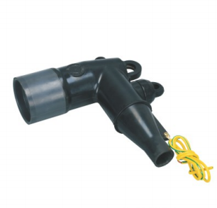
A loadbreak elbow connector can form the main removable interface between the cable and equipment, while compatible bushing inserts, casing seats and extension components help complete the equipment-side connection. Where the network requires several cable paths, a loadbreak junction or pass-through component can provide additional connection points without changing the basic interface structure.
Grounding elbows, insulation caps and elbow surge arresters can then be added according to the maintenance and protection requirements of the installation. For example, YIEOU options such as the JY ZT-15/200 loadbreak elbow connector, JY MP-15kV loadbreak junction and JY JDZT-15/200 grounding elbow can be used within different 200A connection arrangements.
Rather than selecting each item independently, these Medium Voltage Cable Accessories should be coordinated as one complete system. Cable dimensions, equipment interface, voltage class, current rating and operating procedure must all be confirmed before the final component combination is determined.
Conclusion
Cable connection failures often begin with small details. A loose contact, damaged insulation surface, incompatible bushing or contaminated interface may remain unnoticed until the connection begins to overheat or discharge.
A correctly selected Separable Connector helps control these risks by creating a defined electrical, insulating and mechanical transition between the cable and the equipment.
Its removable structure can also make installation, testing, cable replacement and network expansion more manageable. These advantages are especially useful in transformers, ring main units, switchgear, compact substations and cable branch boxes.
Reliable performance still depends on complete system coordination. The cable conductor, insulation diameter, contact component, equipment bushing, grounding arrangement and related Medium Voltage Cable Accessories must all be compatible.
Installation quality is equally important. Accurate cable preparation, correct crimping, clean interfaces, full insertion, secure grounding and adequate cable support determine whether the connection performs as intended.
YIEOU provides American-style cable connection solutions for 15kV and 24kV 200A systems, including loadbreak elbow connectors, bushing inserts, casing components, junctions, grounding elbows, insulation caps and elbow surge arresters. By matching the correct YIEOU Separable Connector with the cable, equipment interface and operating environment, a medium-voltage system can achieve a safer, more maintainable and more reliable connection.