
Replacing medium-voltage equipment often leaves the existing cable circuit in serviceable condition. That can make the cable connection look like the easy part of the project: remove the old connector, fit a new one, and return the circuit to service. The difficulty appears when the replacement transformer, RMU, switchgear panel, or cable branch box uses a different bushing system. A familiar cable size and a similar current label do not make two connector families interchangeable. A successful Separable Connector Retrofit has to rebuild the complete relationship between the equipment interface, connector body, conductor contact, cable adapter, operating method, and available compartment space.
Quick Answer
A Separable Connector Retrofit between 200A loadbreak, 600A American-style deadbreak, and 630A European-style systems is normally an interface conversion, not a like-for-like connector replacement. Each family can use a different equipment bushing, contact arrangement, cable entry geometry, accessory set, and operating procedure. The existing cable may sometimes remain, but only after its conductor construction, cross-sectional area, insulation diameter, screen design, and bending condition are checked against the new complete kit.
YIEOU manufactures medium-voltage cable accessories for these distinct connection systems. In a Separable Connector Retrofit review, we first identify the installed equipment bushing and the interface on the replacement equipment. We then match the cable-side components and confirm whether the original layout can support the new connector envelope. This prevents a current rating or a familiar external shape from being treated as proof of compatibility.
A Retrofit Begins at the Equipment Bushing
The equipment bushing determines the physical and electrical mating interface. It establishes the contact geometry, insulation surface, engagement method, and the accessories that can connect to the apparatus. For that reason, a Separable Connector Retrofit should begin with the bushing drawing and marking rather than with the existing cable cross-section.
A 15kV 200A loadbreak elbow may mate with a compatible loadbreak bushing insert or integral loadbreak bushing. A 15kV or 24kV 600A American-style deadbreak arrangement may use a T-shaped connector and a corresponding 600A apparatus interface. A 24kV 630A European-style front connector belongs to another interface system and connects to the specified European-style equipment bushing. These descriptions refer to coordinated systems. They are not three sizes of one universal plug.
This distinction matters most when replacement equipment is sourced from a different design family. The cable schedule may remain unchanged, yet the equipment supplier may provide a bushing that is mechanically incompatible with the installed connector. An adapter is not automatically available or appropriate. The Separable Connector Retrofit decision may instead require a new connector kit, a different equipment bushing, revised cable positioning, or a planned cable extension.
Our Separable Connector Retrofit review for American-style systems starts with the old and new bushing information. Photographs help identify the general arrangement, but a dimensional drawing, equipment schedule, or confirmed interface designation gives a much stronger basis for matching.
The Three Common Systems Solve Different Operating Problems
The common 200A, 600A, and 630A families are easiest to compare by looking at the job each connection performs. The current number matters in a Separable Connector Retrofit, but it does not explain the full operating role.
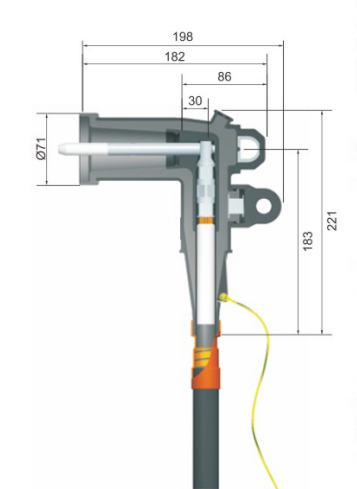
A 200A loadbreak system is often used where a compact elbow connection and a defined loadbreak function are required. YIEOU’s JY ZT-15/200 is a 15kV, 200A loadbreak elbow for a compatible interface. Its product information identifies a loadbreak probe, screened EPDM body, grounding lead, and a cable-side connection that must be selected for the actual cable. The loadbreak designation does not mean that any energized operation is acceptable. The complete matched system, rating, approved tool, operating condition, and local procedure still control the work.
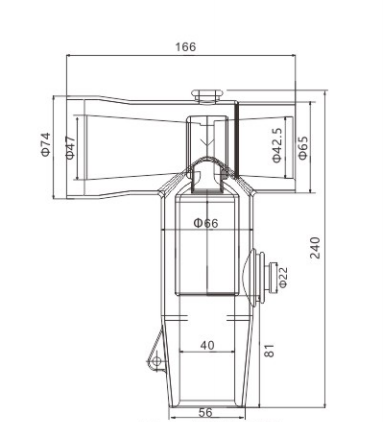
A 600A American-style system serves higher-current equipment connections and is normally treated as deadbreak. The JY QJT-600 is a 15kV/24kV, 600A T-shaped American front connector designed for the corresponding apparatus and cable-accessory interfaces. Its three-port form supports an equipment-side connection and cable-side arrangement within that product system. It is not a load-switching device, and it must not be separated while carrying load current.
A 630A European-style front connector also supports higher-current equipment connections, but its current value does not place it in the 600A American interface family. The JY QJT-24/630A is a 24kV fully shielded European-style front connector. Its published selection data pairs conductor cross-section with insulation diameter and cable-adapter information, showing that the cable fit is part of the product selection rather than an afterthought.
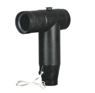
Table 1. Interface Changes in a Separable Connector Retrofit
| Comparison point | 200A loadbreak elbow system | 600A American-style deadbreak system | 630A European-style front connector system |
|---|---|---|---|
| Typical connection form | Compact elbow on a compatible loadbreak interface | T-shaped connector on the specified 600A apparatus system | Front connector on the specified European-style equipment bushing |
| Operating category | Loadbreak only within the rating and approved procedure of the complete system | Deadbreak; de-energize, isolate, verify, and ground before separation | Detachable screened connection; operating method follows the specific equipment and connector system |
| Main retrofit concern | Bushing insert or integral bushing, probe system, elbow envelope, operating access | Apparatus interface, T-body/contact arrangement, rear or branch accessories, space | Equipment bushing type, cable adapter, contact, front/rear arrangement, cable space |
| Cable information needed | Conductor, cross-section, insulation diameter, cable construction | Conductor, cross-section, insulation diameter, contact selection | Conductor, cross-section, insulation diameter, adapter code, cable construction |
| Why current alone is insufficient | Other 200A interfaces may not share the same mating system | A 600A label does not define every apparatus or accessory interface | 630A is not evidence of compatibility with a 600A American-style system |
Changing Current Class Changes More Than Capacity
Moving from 200A to 600A or 630A is sometimes described as an upgrade, but that wording can hide the physical scope of the Separable Connector Retrofit. The higher-current connector is generally larger, uses a different contact path, and requires another equipment interface. It may also change the position at which the cable enters the connector and the direction in which installation force or tightening torque is applied.
The replacement equipment has to provide the correct bushing from the start. If a transformer originally used 200A loadbreak wells and inserts, fitting a 600A deadbreak connector is not achieved by choosing a larger elbow. The equipment-side hardware, conductor path, cable compartment, and operating plan all change. In some projects, retaining the 200A interface remains the more practical Separable Connector Retrofit decision even when the replacement equipment can be ordered with other options. In others, the circuit duty or standardization plan justifies a full conversion.
The same caution applies to a move between 600A and 630A. Their numerical ratings are close, but their interface systems may be different. A 600A American T-shaped connector and a 630A European front connector can use different equipment cones, contact arrangements, installation components, and standards. A Separable Connector Retrofit cannot treat the 30A difference as the only design question.
The real capacity check covers the full current path. The cable conductor, contact or lug, connector, equipment bushing, and internal equipment connection must all support the required duty. Increasing the connector current class does not increase the capacity of an undersized cable or an unsuitable equipment terminal. Conversely, a circuit operating below 600A does not make every 600A product a valid replacement for a 200A interface.
Existing Cable Dimensions Decide What Can Be Reused
Keeping the installed cable can reduce excavation, jointing, and outage scope, but cable reuse must be proven. The conductor cross-sectional area is only one input. A Separable Connector Retrofit also needs the conductor material and construction, the diameter over the prepared insulation, the cable insulation system, the screen arrangement, and the condition of the cable at the existing termination.
The conductor data controls contact selection in every Separable Connector Retrofit. Copper and aluminium conductors may require different terminals or preparation. Compacted and conventional stranded conductors with the same nominal cross-section can have different dimensions. The contact range and the specified crimping or mechanical connection method must suit the actual conductor.
The insulation diameter controls the fit between the cable and the stress-control or adapter components. Two cables marked with the same square-millimetre size can have different insulation diameters because of voltage class, insulation design, manufacturer, or construction. A body or adapter that is too loose cannot create the intended electrical interface. One that is too tight may be damaged during installation or fail to reach its correct position.
Cable condition matters as well. The original connector preparation may have removed more cable length than the new kit requires, or the exposed end may have heat damage, moisture, corrosion, deep insulation cuts, or an unsuitable semiconductive-screen transition. Removing the old accessory can also shorten the usable cable. The retrofit plan should therefore include enough length to cut back to sound material and prepare the cable according to the new product instruction.
This is why a Separable Connector Retrofit often needs both the original cable datasheet and site measurements. When documentation is incomplete, measuring the insulation diameter and confirming the conductor after safe removal can prevent a kit from being selected on a nominal cable size alone.
Compartment Space Can Block an Electrically Correct Conversion
An electrically compatible Separable Connector Retrofit can still be impractical if it does not fit the equipment compartment. The new body needs room for installation, grounding, cable bending, phase spacing, and any rear accessory or protective cap. The cable must approach the bushing without using the connector to force the route into alignment.
A 200A elbow can occupy a relatively compact envelope, yet it still requires room for the approved operating tool and a clear pulling direction. A 600A T-shaped connector is larger and may extend farther from the bushing face. If the system includes a second cable, rear connector, arrester, cap, or bus component, the complete stack becomes longer. A 630A European front connector may have another cable entry and adapter arrangement that changes the required depth and bending space.
The cable support position deserves particular attention. A heavier connector does not correct a cable that arrives too high, too low, or at an angle. Continuous bending force can interfere with engagement during installation and load the equipment bushing during service. Moving or adding the support bracket may be a necessary part of the Separable Connector Retrofit.
Phase-to-phase layout also matters in a Separable Connector Retrofit. The body of one connector, its earth lead, or a rear accessory must not obstruct the neighboring phase. Doors and internal barriers must close without pressing on the cable accessories. If the proposed connector only fits after forcing the cable or removing a required barrier, the layout is not ready for installation.
A practical Separable Connector Retrofit drawing shows the bushing centres, compartment depth, neighboring phases, cable entry position, support points, and connector envelope. We can compare that information with our product dimensions before the project reaches the outage stage.
Operating Procedures Must Change With the Connector Family
The operating method is one of the most important differences in a Separable Connector Retrofit. A crew familiar with a 200A loadbreak elbow must not carry the same assumptions into a 600A deadbreak connection. Equipment labels, work instructions, training, tools, and switching plans should reflect the new connector family.
For a properly rated 200A loadbreak system, specified load-make or loadbreak operations may be possible under the conditions defined for the complete system. That does not authorize casual removal, operation outside the current rating, work with an unmatched bushing, or use of an improvised tool. The connector and its mating component have to form the intended loadbreak interface.
A 600A deadbreak connector does not perform the function of a load switch. Before separation, the circuit must be de-energized and handled under the applicable isolation, voltage-verification, and grounding procedure. The switching function belongs elsewhere in the distribution equipment. Describing the connector as removable does not change that boundary.
European-style 630A systems also require the procedure specified for the actual connector and equipment. The general word Connector does not define whether a medium-voltage accessory can interrupt load current. That ability comes from the tested product system and its operating category.
Changing the interface without changing the operating documentation creates a human-factors risk. A Separable Connector Retrofit package should therefore identify the new family clearly and remove obsolete labels or instructions. The Separable Connector Retrofit handover should state which components are loadbreak, which are deadbreak, what accessories are installed, and what tools and procedures apply.
Supporting Accessories Must Belong to the New System
The visible connector body is only one part of the assembly. A Separable Connector Retrofit may also affect bushings, inserts, contacts, cable adapters, insulated caps, grounding accessories, surge arresters, junctions, rear connectors, and test provisions. Reusing a convenient-looking accessory from the previous system can defeat the purpose of a correctly selected main connector.
In a 200A loadbreak arrangement, the elbow, probe, bushing insert or integral bushing, cap, grounding elbow, junction, and arrester options must be compatible with the same interface. The capacitive test-point provision, when required, should be confirmed on the exact product configuration.
A 600A deadbreak arrangement may use T-bodies, apparatus bushings, bus or junction components, extensions, rear accessories, caps, or grounding components designed for that system. The accessory position affects both electrical compatibility and the physical depth of the installation.
A 630A European-style arrangement can use a front connector with a rear connector or other matched accessory, depending on the equipment design and circuit layout. The equipment interface, front/rear sequence, cable adapter, conductor contact, and protective components should be specified together.
This complete-kit approach also improves Separable Connector Retrofit spare-parts planning. A site converting one feeder should not assume that the old and new spares can be mixed because both are described as medium-voltage separable accessories. Each spare should be labelled with the voltage class, current class, interface family, and compatible product application.
Our Separable Connector Retrofit review for European-style systems covers the connector and the associated cable-side and equipment-side components. This makes the bill of materials reflect the actual interface conversion instead of listing one rubber body as if it completed the project.
Plan the Retrofit Around Evidence and the Outage Sequence
A good Separable Connector Retrofit plan separates what can be confirmed before the outage from what must be verified after safe access is available. Before the outage, the team can collect equipment drawings, bushing markings, connector models, cable schedules, photographs, load data, and compartment dimensions. Those records normally establish the proposed product family and reveal major layout problems.
Some Separable Connector Retrofit details may remain uncertain until the old connector is removed. The exact cable insulation diameter, condition of the prepared surface, remaining cable length, conductor construction, and hidden equipment-side condition may require direct inspection. The work plan should allow for that verification rather than treating the new kit as automatically final.
The outage sequence should protect the cable and bushing. After the circuit is de-energized, isolated, verified, and grounded under the site procedure, the old components can be removed with the specified tools. The cable end and equipment interface can then be inspected and compared with the approved retrofit data. Damaged or contaminated mating surfaces need to be addressed before the new assembly is installed.
Separable Connector Retrofit installation follows the instruction for the selected product, including cable preparation dimensions, contact installation, cleaning, lubrication, engagement, tightening, grounding, and final checks. Experience with another connector family is not a substitute for those instructions. Commissioning tests and inspection records should identify the exact new assembly.
When customers send us the old and new equipment drawings, bushing details, cable datasheet, measured insulation diameter, conductor information, circuit duty, and compartment layout, we can match the Separable Connector Retrofit components more accurately. Clear information also helps us identify questions that must be resolved on site before the outage can be closed.
Conclusion
A Separable Connector Retrofit across 200A loadbreak, 600A American-style deadbreak, and 630A European-style systems changes an interface ecosystem. The equipment bushing comes first, followed by the connector family, cable contact and adapter, operating method, accessories, cable condition, and available space. A current label or cable cross-section cannot confirm interchangeability on its own.
YIEOU can match the required connector system when the project information describes both sides of the connection. Treating the Separable Connector Retrofit as a complete interface conversion produces a clearer bill of materials, a more realistic outage plan, and an operating procedure that reflects the installed product.
FAQ
Can a 200A loadbreak elbow be replaced directly by a 600A T connector
Usually not. The 600A connector normally requires a different apparatus interface, contact arrangement, accessory set, and installation envelope. A direct change is possible only when the equipment and complete connection system were specifically designed for that conversion.
Are 600A American and 630A European connectors interchangeable
No. Similar current ratings do not prove a common equipment bushing, contact geometry, standard, or accessory system. The interface designation and dimensional information must be confirmed independently.
Can the original medium-voltage cable remain in a Separable Connector Retrofit
It may remain if its voltage class, conductor, cross-section, insulation diameter, screen construction, condition, remaining length, and bending route suit the new kit. Reuse should be confirmed from the cable data and safe site measurements.
Is cable cross-section enough to select the new adapter
No. The diameter over insulation is a separate and essential selection value. Conductor material and construction, voltage class, and cable design also affect the contact and adapter choice.
Does a larger connector increase the feeder capacity
Not by itself. The cable conductor, contact, connector, bushing, and equipment terminal all form the current path. The capacity of the complete circuit is limited by its coordinated design, not by the largest printed connector rating.
Can a 600A deadbreak connector be used for routine load switching
No. A deadbreak connector is not a load-switching device. It must be separated only after the circuit has been de-energized and handled according to the applicable isolation, verification, and grounding procedure.
What information should be sent for a retrofit review
Useful information includes the old and new equipment drawings, bushing markings and dimensions, existing connector model, cable datasheet, conductor details, measured insulation diameter, circuit voltage and current, compartment layout, and required accessory arrangement.