
Across a solar farm, several transformer stations may look almost identical from the service road. Inside their cable compartments, however, a different bushing or an additional outgoing feeder can change the cable accessory arrangement. The connector beside a transformer belongs to the AC collection system, with requirements determined by that equipment and its cables. It cannot be selected from the inverter’s DC specifications. For a Separable Connector, the useful starting point is the actual connection at each station: where the cable arrives, which interface it meets, and whether that point carries one transformer branch or a combined feeder.
Quick Answer
A Separable Connector fits a solar collection system when its equipment interface, voltage class, current duty and cable accommodation all match the particular connection. A fixed American-style 600A deadbreak Separable Connector, a 200A loadbreak branch and a European-style 630A connection are separate systems. Similar appearance or nearby current ratings do not make them interchangeable.
At YIEOU, we manufacture medium-voltage cable accessories for equipment connections, including American-style accessories used at photovoltaic step-up substations. Our range includes front connectors, integrated bushings and mixed-current busbars. Their practical value lies in forming compatible connections at the transformer or distribution enclosure while keeping the cable arrangement accessible for planned work.
Begin at the AC equipment interface
The collection cable carries AC power away from a transformer station toward other distribution equipment. Its termination needs to suit the transformer’s medium-voltage bushing or the receiving switchgear. Solar modules and DC combiner circuits use different connection arrangements. A Separable Connector for the MV cable is therefore part of a particular equipment interface, rather than an accessory selected simply because the site generates solar power.
This distinction becomes useful when transformer packages come from different equipment suppliers. Two stations with similar power duties may use different bushing systems. An accessory that mates correctly at the first station can be unsuitable at the second, even if both cable schedules show the same conductor cross-section. Separable Connector matching begins with the bushing geometry, contact arrangement and insulation engagement specified for each package.
We offer Separable Connector arrangements within our American cable accessory range for compatible equipment. Where a station instead uses a European interface, the connection must follow that system. The application name does not create compatibility between the two. Keeping each connection within its intended interface family also makes the relevant caps, bushings and other accessories easier to distinguish during station assembly.
A practical example is a collection feeder passing through a station beside a transformer branch. The two paths may occupy the same compartment, but they do not automatically use the same accessory. The equipment arrangement determines whether they meet separate bushings, a suitable junction or an engineered branching assembly. The front of the enclosure alone rarely explains this relationship. For transformer OEMs and solar project contractors, that distinction keeps the connection tied to the equipment package being installed.
Separate the feeder duty from the transformer branch
An outgoing cable can carry the contribution of more than one connected transformer. Its current duty can consequently differ from that of an individual transformer branch. This affects the conducting path through the accessory assembly as well as the cable. A Separable Connector rating describes the product’s specified capability; it does not set the allowable loading of the entire collection circuit.
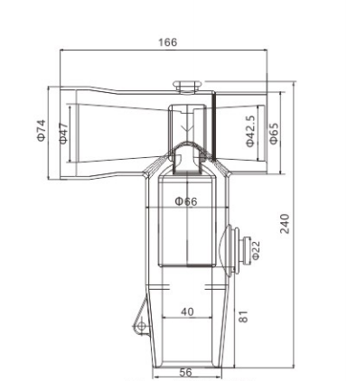
Where a station uses the corresponding American-style bushing, a T-shaped front accessory can provide the fixed cable connection and specified branching arrangement. We manufacture this structure in our JY QJT-600 range, with 600A deadbreak configurations for 15kV and 24kV arrangements. This Separable Connector suits the connection through its interface and structure together. The 600A marking alone does not establish that every cable branch or mating component can carry the same current.
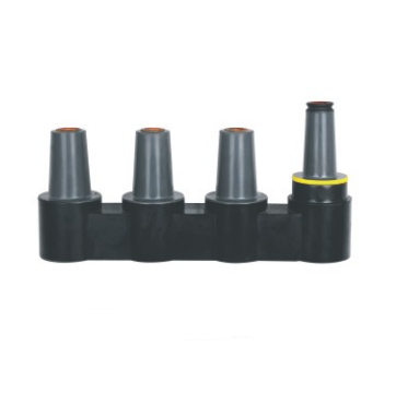
Our mixed-current busbar range also illustrates why the complete current path matters. A busbar can combine compatible 600A and 200A interfaces within a specified assembly. The presence of both ratings does not convert a 200A outlet into a 600A branch. Each outlet and the shared path retain their own limits, and the operating function of each interface remains distinct.
For a Separable Connector serving an individual transformer, the branch load may be lower than the combined feeder duty. That can support a different product direction when the equipment is designed for it. It does not justify substituting a lower-rated interface at an existing higher-rated bushing. The connection has to satisfy the equipment arrangement and electrical duty together.
Voltage class follows the collection network
Solar capacity is not a voltage specification. A larger plant may use a different collection voltage, but plant size by itself cannot identify the required accessory. The Separable Connector voltage class follows the actual cable system and connected equipment, including the insulation requirements of that particular connection.
Within our American-style front connector range, the 15kV and 24kV versions address corresponding applications. They are specific configurations. A product family name covering both classes does not mean that one supplied component has every rating listed across the family. The installed version, its mating accessory and the equipment bushing need to belong to the intended voltage arrangement.
The same logic applies where a project uses 35kV equipment. A lower-voltage accessory cannot become suitable through a change of cable lug or the addition of an insulating cover. A separate product configuration and the corresponding equipment interface are required. We keep these distinctions explicit because the outside shape of a screened accessory gives only a limited indication of its internal insulation dimensions.
This becomes visible when adjacent collection sections use different equipment packages. A Separable Connector suitable at a 15kV-class American interface does not establish the accessory direction for a higher-voltage station nearby. The equipment boundary needs to remain clear even if the enclosures share a site layout. Keeping the voltage configuration tied to each actual connection also prevents a spare accessory from being treated as universal stock for the entire plant.
In an expansion, the existing station’s voltage class can also constrain the new connection. Adding solar capacity does not automatically change the network voltage, and retaining the voltage does not guarantee that the original interface has spare current capacity. Voltage suitability and current suitability answer different questions. A Separable Connector must meet both without treating either as a substitute for the other.
Cable fit involves two different contact surfaces
At the cable end, the conductor contact carries current while the accessory body engages the cable insulation. These are related but different fits. Conductor area helps determine the contact configuration. Diameter over insulation helps determine whether the insulating interface can engage correctly. A Separable Connector needs both relationships to be right.
Two cables marked with the same square-millimetre size can have different insulation diameters. Their voltage class, construction and manufacturing dimensions can differ. Selecting an accessory only from conductor area can therefore produce a suitable-looking contact inside a poorly matched insulating body. Increasing assembly force does not correct that mismatch and can damage the surfaces that need to remain intact.
Conductor material and construction also affect the electrical connection. Copper and aluminium conductors require an appropriate contact arrangement and the specified preparation. A flexible conductor is not automatically accommodated by a contact intended for another construction. We manufacture cable accessory configurations around these actual cable characteristics, rather than treating nominal area as a complete description of the cable end.
At a solar station, cable routing adds another influence. A long feeder arriving from a trench may be heavy and resistant to the final change in direction. Its support needs to carry that mechanical load before it reaches the Separable Connector. The connector can then perform its intended electrical and insulating role without being used to pull a displaced cable into line with the bushing.
The bushing and accessory form one mating connection
The Separable Connector and equipment bushing work together at the separable interface. Correct engagement brings the conductive contacts and insulating surfaces into their intended positions. Neither component can compensate for an incompatible counterpart. A Separable Connector selected independently of its bushing leaves the most important fit unresolved.
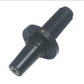
Our American integrated deadbreak bushing range provides equipment-side interfaces for compatible American-style arrangements, including applications at photovoltaic substations. Where that bushing system is used, the cable accessory needs to match its specified version. The bushing’s mounting and equipment integration also remain part of the finished connection. Replacing the cable-side part does not correct an unsuitable equipment-side installation.
This is especially relevant when a station combines supplied transformer equipment with separately assembled cable accessories. The visible front connection may be only one part of the assembly. Behind it, the bushing passes into the equipment, while the cable-side body must engage the exposed interface correctly. Both sides have to retain their intended position when the cable is supported and the compartment is closed.
| Connection situation | Product direction | What still governs the fit |
|---|---|---|
| Fixed American-style feeder connection | Compatible 600A deadbreak arrangement | Bushing version, voltage class and complete current path |
| Individual branch designed for 200A accessories | Matched 200A loadbreak system | Branch duty, equipment interface and permitted operating conditions |
| Equipment supplied with a European-style interface | Corresponding European accessory system | Exact bushing interface and cable configuration |
| Additional outlet within a specified busbar assembly | Compatible branch accessory | Outlet rating, shared path and available working space |
The table describes directions for different equipment arrangements. It does not provide a cross-system substitution list. Moving from one row to another generally involves an equipment configuration decision, rather than exchanging a cable end on the same bushing.
For example, a Separable Connector and integrated bushing may form a suitable fixed transformer connection, while a separate mixed-current assembly serves another distribution point. Their presence on the same project does not mean all three products belong together at every station. The useful configuration is the one that matches that station’s actual cable paths and equipment interfaces, without adding unused connection parts simply to standardise appearances.
Compact stations still need usable cable space
A screened Separable Connector can make a compact equipment connection possible, but the cable still needs room to bend, settle and remain supported. The important space is the usable volume around the assembled connection. An empty compartment can look generous until the actual feeder cables, supports and outgoing accessories occupy it.
Our T-shaped American front connection is relevant where the equipment layout calls for that structure. Its overall arrangement needs to suit the direction of the cable and the space for associated accessories. Turning a cable sharply to make the door close can transfer sustained force into the contact area or cable adapter. A compact accessory does not remove the cable’s own bending requirements.
Where a station has several cable entries, the route to one connection can obstruct another. The first installed cable may appear satisfactory while leaving insufficient room for the remaining phases or another feeder. The finished arrangement needs to keep the interfaces reachable and the cable supports effective. The physical layout of the Separable Connector assembly matters throughout the full compartment, rather than only at its front face.
There is also a difference between installation clearance and service clearance. A connection assembled before a removable panel is fitted may be difficult to reach after construction. Access for the specified tools and planned work needs to survive the final enclosure arrangement. This is a product integration issue: a connection that fits inside the enclosure still needs to be usable in its installed position.
Outdoor exposure reaches the whole connection assembly
At a solar site, dust can collect during construction before the cable compartment enters normal service. Moisture can arrive through cable entries or enclosure defects. A sealed Separable Connector helps protect its intended interface when correctly matched and assembled, but the enclosure, cable entry and supporting structure have their own environmental responsibilities.
Screening and grounding also need to remain continuous through the completed arrangement. Our relevant American cable accessories include grounding provisions as part of their connection structure. These features need the specified connections in the installed assembly. The Separable Connector’s screened outer surface is not permission to handle an energised accessory or to omit the equipment’s grounding arrangements.
The Connector interface depends on sound mating surfaces as well as sound conductive contacts. Dirt trapped during assembly can affect the fit even when the outside later looks clean. Protecting the accessory during storage and cable preparation is therefore directly related to the connection’s insulation performance, rather than being a cosmetic concern.
Severe salt exposure, unusual pollution or conditions outside a product’s normal limits need an appropriate configuration. We offer application-specific support within our cable accessory range, with suitability determined for the actual product and environment. A Separable Connector described for indoor and outdoor use does not establish unrestricted suitability for every exposed solar site or every condition inside a poorly sealed enclosure.
Expansion needs a connection plan that preserves operating limits
An additional transformer station may require another feeder connection at an existing distribution point. A reserved interface can make this arrangement possible when it was included in the equipment configuration. It does not guarantee spare current capacity, cable space or a permitted live connection procedure. A Separable Connector supplies a defined connection function within those wider equipment limits.
For deadbreak connections, separation is carried out in the required de-energised and isolated condition. The term separable describes the interface structure. It does not give the accessory a load-switching function. The station’s switching equipment and approved operating procedure govern how the circuit is made ready for work.
An unused operating interface also needs the appropriate rated insulating accessory. A transport cover protects a component during handling; it is not automatically suitable for a port that will be energised. Our accessory range includes interface protection products for compatible arrangements. Their voltage class, interface and intended use remain part of the completed station configuration.
At YIEOU, our manufacturing support includes dimensional and electrical verification, with high-voltage and partial-discharge testing capabilities according to the product requirements. Those checks support the supplied accessory. The installed cable preparation, bushing engagement and grounding still determine how the finished Separable Connector assembly performs at the station. For a solar collection point, the right result is a matched connection that suits the actual feeder or transformer branch and retains access for its intended service life.
FAQ
Is a solar MV Separable Connector used on the DC side?
No. The connection discussed here is on the medium-voltage AC collection side of the transformer station. Solar modules, DC strings and combiner equipment use their own specified connection products.
Can a 600A connector replace a 630A connector?
The current numbers do not establish compatibility. American-style 600A and European-style 630A systems can have different interfaces and mating structures, so the actual equipment bushing governs the accessory direction.
Does a larger solar plant always need a higher-voltage accessory?
The actual collection voltage and equipment insulation requirements determine the voltage class. Plant capacity alone cannot establish the correct accessory, and current duty still needs separate consideration.
Why is cable cross-section insufficient for selecting a Separable Connector?
The conductor contact and cable insulation interface have different matching requirements. Diameter over insulation, conductor material and construction matter alongside nominal conductor area and voltage class.
Can a deadbreak connection be separated while carrying load?
No. Deadbreak accessories do not perform load switching. The circuit requires the specified de-energised and isolated condition before the connection is separated under the applicable procedure.
Does a spare interface guarantee that another transformer can be added?
No. The outlet rating, shared current path, protection arrangement, cable route and service access still limit the expansion. The unused interface also needs appropriate insulation for its operating condition.