
A cable branch box is not simply an enclosure containing several medium-voltage cable connections. It may divide one incoming feeder into multiple branches, continue a ring network, provide circuit isolation points or reserve positions for future expansion.
The correct Separable Connector configuration therefore depends on the function of each circuit. A 200A branch connection, a 600A or 630A main feeder and an unused energized interface should not be treated in the same way.
Before selecting connectors, the project should confirm the system voltage, circuit current, cable construction, equipment interface and internal layout. These factors determine not only which Separable Connector is required, but also whether junctions, rear connectors, insulating caps, grounding accessories or surge arresters are needed.
YIEOU manufactures American-style and European-style medium-voltage cable accessories for cable branch boxes and related distribution equipment. This allows the connector, interface and auxiliary accessories to be considered as one configuration rather than as separate products.
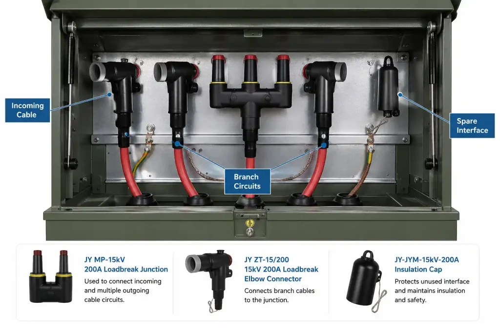
Define What Each Cable Position Must Do
The configuration should begin with the single-line diagram, not with the number of connector ports inside the box.
Every interface needs a clear circuit function.
Mark each position as one of the following:
- Main incoming feeder
- Main outgoing or ring feeder
- Individual branch feeder
- Future expansion position
- Grounding or testing position
- Surge-protection position
Two cable branch boxes may have the same number of interfaces but perform completely different functions.
For example, a ring-network branch box may contain one incoming feeder, one outgoing feeder and two transformer branches. The incoming and outgoing cables form the main circuit, while the other two cables supply separate loads.
A radial branch box may instead have one incoming feeder and several outgoing branches. It does not need a ring outgoing position, but the incoming circuit may carry the combined current of all downstream branches.
The main circuit must be sized for the total current path.
Suppose three branch circuits normally carry 80A, 100A and 120A. Each branch may remain within a 200A connection rating, but the incoming feeder may carry close to their combined load.
This means a 200A connection cannot automatically be used for the incoming circuit simply because every individual branch is below 200A.
The main feeder rating should consider:
- Expected simultaneous load
- Future capacity growth
- Cable current capacity
- Permitted operating margin
- Network protection design
The circuit function should be confirmed before the connector family is selected.
Operating requirements also matter.
Some branches may need to be disconnected during maintenance or network reconfiguration. Others may remain connected throughout normal operation and only be removed after the circuit is fully isolated.
This affects whether the position requires a loadbreak or deadbreak connection system.
A loadbreak connector is designed for specified switching operations, but it must still be operated with the correct tools and approved procedures. A deadbreak connector must not be disconnected while carrying load current.
The project should therefore define both the electrical duty and the intended operating method of every circuit.
Match the Current Rating and Interface Family
The Separable Connector must match the branch box interface. Similar appearance or identical voltage markings do not guarantee compatibility.
Main and branch circuits may use different current classes.
American-style cable systems commonly use 200A loadbreak connectors for branch circuits and higher-current interfaces for main feeders. A cable branch box may therefore contain both 200A and 600A connection positions.
European-style systems often use screened 630A front connectors for main cable connections. Compatible rear connectors can then be added where an additional cable branch or surge arrester is required.
The selected arrangement depends on the branch box design rather than on one universal rule.
Cable Branch Box Configuration Guide
| Circuit position | Typical configuration | Check first |
| Main incoming feeder | 600A or 630A connection | Total feeder current |
| Ring outgoing feeder | Same family as main input | Ring continuity |
| Individual branch | Often 200A loadbreak | Branch current |
| Additional European branch | Front and rear connectors | Available depth |
| Energized spare position | Rated insulating cap | Interface type |
| Grounding position | Matching grounding accessory | Safety procedure |
| Surge-protection position | Connector-type arrester | System protection design |
This table is only a quick configuration guide. The final current rating and interface must follow the actual system design.
A higher current rating is not automatically a better choice.
A 630A connector should not be selected only because it offers more current capacity. It must also match:
- The branch box bushing
- The cable conductor
- The cable insulation diameter
- The available installation space
- The required operating method
Similarly, a physically compact 200A elbow may appear suitable for a small branch cable, but the interface standard and future load still need to be checked.
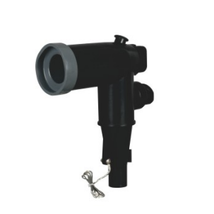
Keep the connection system compatible from end to end.
A complete 200A connection may include:
- Loadbreak elbow connector
- Bushing insert
- Junction
- Insulating cap
- Grounding elbow
- Elbow-type surge arrester
These components must belong to the same compatible interface system.
YIEOU can coordinate the Separable Connector with matching junctions, caps, grounding accessories and other medium-voltage cable components. This reduces the risk of receiving parts with the correct voltage rating but incompatible mechanical interfaces.
Configure Each Position as a Complete Connection
Once the circuit functions and interface families are clear, each position can be configured separately.
The incoming feeder carries the greatest responsibility.
The incoming position should be checked against:
- Rated system voltage
- Maximum operating voltage
- Continuous current
- Short-time current requirements
- Cable conductor size
- Cable insulation diameter
- Branch box interface
- Installation environment
In a ring system, the outgoing feeder usually requires a similar connection class because it continues the main current path.
However, the incoming and outgoing cables may enter the enclosure from different directions. Their bending space and cable supports should therefore be checked independently.
Branch connectors should follow the branch circuit design.
A branch supplying a transformer or another distribution point may carry much less current than the main feeder. Even so, the connector should not be selected only according to the present operating current.
The project should also consider:
- Planned transformer capacity
- Possible future load growth
- Cable current rating
- Switching frequency
- Fault-current duty
- Maintenance requirements
A branch currently carrying 100A may use a 200A system, but only after confirming that the interface and future operating conditions remain suitable.
Junctions should reflect the actual circuit topology.
A junction can connect several cable circuits to a common internal conductor. It may be used for branching, looping, sectionalizing or extending a feeder.
The number of junction positions should follow the single-line diagram. Additional positions can be reserved for future circuits, but each unused energized port must be properly insulated.
Extra ports should not be added without a clear purpose. They increase the number of components, occupy enclosure space and create additional positions that must be protected and identified.
European rear connectors require early planning.
In a European-style system, a rear connector may be installed behind a compatible front connector to add another cable path.
This can be useful when:
- A second branch is required
- A surge arrester must be connected
- Future expansion is planned
- The front interface is already occupied
However, rear-connected arrangements increase the overall depth of the assembly. The enclosure must provide enough room for installation, tightening, cable bending and future removal.
The number of rear-connected components should also remain within the approved connector and equipment configuration.
Match the Connector to the Actual Cable
Nominal conductor size alone is not enough to select a Separable Connector.
Two cables with the same conductor cross-section may have different insulation diameters, conductor structures and screen designs. These differences can change the connector body, contact and cable preparation requirements.
Measure the cable insulation diameter.
The connector body is normally designed for a specific insulation diameter range.
If the cable insulation is too small, the connector may not achieve the intended sealing and stress-control contact. If the insulation is too large, installation may become difficult and the connector body may be overstretched.
The project should provide either:
- The measured insulation diameter
- A complete cable datasheet
- The cable manufacturer and full model designation
The diameter should not be estimated from conductor cross-section alone.
Confirm the conductor material and structure.
The contact component must suit the actual conductor.
Important details include:
- Copper or aluminium
- Conductor cross-section
- Stranded or compacted conductor
- Round or sector-shaped conductor
- Crimping or bolted connection method
For example, two 240 mm² cables may require different contacts when one uses a copper conductor and the other uses aluminium.
Check the cable screen construction.
The connector’s stress-control, shielding and grounding structures must coordinate with the cable layers.
The cable information should identify:
- Insulation material
- Semiconductor screen
- Metallic wire or tape screen
- Outer sheath
- Armour, where applicable
This information also helps installers determine the correct preparation method.
Use interface drawings rather than photographs.
A photograph may show the general shape of a bushing but cannot reliably confirm the interface standard.
The branch box drawing should identify:
- Voltage class
- Current class
- American or European interface
- Loadbreak or deadbreak type
- Bushing dimensions
- Phase spacing
- Installation orientation
These details should be confirmed before production. Trying to identify the interface after the products arrive on site can delay installation and lead to unnecessary replacement costs.
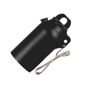
Check the Internal Layout Before Finalizing the Configuration
An electrically correct separable connector may still be unsuitable if the enclosure does not provide enough working space.
Cable bending radius must be respected.
Medium-voltage cables should not be sharply bent immediately below the connector. The minimum bending radius depends on the cable diameter and construction.
The layout should allow each cable to approach the connector without excessive side force.
This is especially important when:
- Several cables enter from the same trench
- Incoming and outgoing cables cross
- Larger replacement cables are installed
- Additional branch circuits are added later
A layout that looks acceptable without cables may become crowded after the actual cable bends are considered.
Operating access must remain clear.
Loadbreak elbows require enough room for the operating tool to reach the pulling eye and move in the intended direction.
Nearby cables, structural supports and the enclosure door should not block the operating path.
European front and rear connectors also need space for:
- Assembly
- Tightening
- Testing
- Removal
- Cable support
A separable connector that can be installed once but cannot be accessed later is not a practical configuration.
Cable weight should not pull on the interface.
The branch box should include suitable cable supports or cleats. The bushing and Separable Connector should not carry the weight of long, unsupported cable sections.
Before confirming the layout, check:
- Cable support positions
- Minimum bending radius
- Phase-to-phase clearance
- Access to test points
- Grounding lead routing
- Door-closing clearance
- Space for insulating caps
- Space for surge arresters
- Water drainage and contamination control
These checks are particularly important when modifying an existing cable branch box.
Treat Spare Interfaces as Part of the Design
A spare interface is not simply an empty position. It must be safe in the current system and practical for future use.
An energized spare needs a rated insulating cap.
A shipping cover or ordinary dust cap does not provide the insulation required for an energized medium-voltage interface.
The insulating cap should match:
- Voltage class
- Current interface
- Mechanical dimensions
- Shielding arrangement
- Grounding requirements
The project drawing should clearly mark whether the spare position is energized, isolated or reserved only as physical space.
Future expansion needs cable space as well as an interface.
A spare port has little value when the future connector cannot be installed because nearby cables block the working area.
The initial layout should reserve:
- Connector body space
- Cable bending space
- Operating-tool access
- Cable entry space
- Cable support positions
Planning these details during the first configuration is easier than modifying the enclosure later.
Coordinate Grounding and Surge Protection
Grounding accessories and surge arresters should be included in the configuration from the beginning.
Grounding accessories support maintenance but do not replace isolation.
A grounding elbow or related accessory may provide a defined grounding position after the circuit has been isolated and absence of voltage has been confirmed.
The project should specify:
- Which circuits require temporary grounding
- Where grounding will be applied
- How voltage absence will be verified
- Which operating procedure will be followed
- Where grounding accessories will be stored
The conductive screen and grounding lead of the connector must also be connected according to the system design.
Surge arresters must match the network, not only the connector.
A connector-type surge arrester may fit physically onto a branch box interface, but electrical compatibility must also be confirmed.
Selection should consider:
- System voltage
- Grounding method
- Arrester rating
- Insulation coordination
- Expected surge conditions
- Protection location
The arrester should remain accessible for inspection and replacement. It should not be hidden behind tightly arranged cables.
Provide Complete Information Before Production
The connector configuration can be confirmed more efficiently when the manufacturer receives complete project data at the beginning.
A model name alone is rarely enough.
Provide the following information:
- Single-line diagram
- System voltage
- Main-circuit current
- Branch-circuit currents
- Required interface type
- Loadbreak or deadbreak requirement
- Cable conductor material
- Cable cross-section
- Cable insulation diameter
- Cable screen structure
- Number of circuits
- Number of spare positions
- Branch box interface drawing
- Cable entry direction
- Indoor or outdoor environment
- Grounding requirements
- Surge-protection requirements
A marked single-line diagram is especially useful. Each interface can be labelled as incoming, ring outgoing, branch, spare, grounding or surge protection.
YIEOU can then match the Separable Connector bodies, contacts, junctions, caps and related accessories according to the same configuration schedule.
Where a project requires non-standard cable dimensions, special interface coordination or OEM supply, YIEOU’s manufacturing and production teams can confirm the details before batch production. This support is most valuable when it prevents incompatible components from entering the same project.
Early confirmation helps avoid common problems such as:
- Incorrect cable diameter range
- Wrong conductor contact
- Incompatible bushing interface
- Missing insulating caps
- Insufficient rear-connector space
- Incorrect number of junction ports
- Mixed accessory systems
The system designer remains responsible for the network rating, protection settings and operating procedures. The manufacturer’s role is to ensure that the supplied connector configuration matches the approved project information.
Frequently Asked Questions
Can every circuit use a 200A Separable Connector?
No. The main feeder may require a 600A or 630A interface.
Is a 630A connector always better?
No. It must match the current, cable, bushing and enclosure.
Can a shipping cap protect an energized spare port?
No. Use a rated insulating cap.
Is cable cross-section enough for selection?
No. Insulation diameter, conductor material and interface type are also required.
Can rear connectors be added later?
Only when the connector system and enclosure space allow it.
Conclusion
A practical Separable Connector configuration should follow five steps:
- Define the function of every cable position.
- Match the current rating and interface family.
- Select the connector and auxiliary accessories as one system.
- Verify the actual cable dimensions and enclosure space.
- Confirm the complete arrangement before production.
The main circuit, branch circuits, spare interfaces, grounding positions and surge-protection points should each have a clear purpose. They should not be configured simply according to the number of available ports.
YIEOU can provide American-style and European-style Separable Connectors, junctions, insulating caps, grounding accessories and related cable branch box components. Send us your single-line diagram, cable data and interface drawing to confirm a suitable configuration for your project.