
Ring main units and compact substations place medium-voltage switching, protection, transformation, and cable connection functions within relatively limited equipment space. This compact structure helps simplify distribution networks, but it also creates stricter requirements for cable routing, equipment interfaces, insulation coordination, and installation access.
A Separable Connector provides an insulated and screened connection between a medium-voltage cable and a compatible equipment bushing. Depending on the equipment design, the connection may use a 200A loadbreak elbow connector, a higher-current deadbreak connector, a T-shaped connector, or a coordinated combination of bushings, caps, grounding accessories, busbars, and surge arresters.
For ring main units and compact substations, connector selection should begin with the actual equipment layout rather than with a product photograph or voltage label alone. The system voltage, rated current, bushing interface, cable dimensions, cable-entry direction, phase spacing, operating method, and maintenance requirements must all be confirmed before the connector model is finalized.
YIEOU manufactures 200A loadbreak and 600A deadbreak Separable Connector products together with equipment-side interfaces and related medium-voltage cable accessories. This allows the cable-side connector, equipment bushing, protective component, and maintenance accessory to be reviewed as one complete connection arrangement.
Why Are Separable Connectors Suitable for Ring Main Units?
A ring main unit, commonly referred to as an RMU, is used to control and distribute power within a medium-voltage ring network. It may contain load switches, circuit breakers, fuse-switch combinations, protection devices, busbars, and cable compartments.
The cable compartment is usually compact. Incoming and outgoing cables often enter from the bottom and must connect to equipment bushings positioned above the cable-entry plate. This arrangement limits the available bending space and makes the connector shape, cable stiffness, and interface position particularly important.
A properly selected Separable Connector supports several practical requirements inside an RMU:
- It encloses the cable-to-equipment connection within an insulated structure.
- It maintains the screened connection arrangement when correctly grounded.
- It allows the cable interface to be disconnected according to the connector’s operating category and approved procedure.
- It helps organize cable routing inside a restricted compartment.
- It can work with protective caps, grounding accessories, surge arresters, and extension components.
- It supports standardized connection arrangements across repeated RMU panels.
However, the connector cannot compensate for an unsuitable cabinet layout. The RMU design still needs sufficient phase spacing, cable bending clearance, access for installation tools, and room for connector removal.
Cable Entry and Bending Space
Most RMU cables enter vertically from below. After passing through the cable-entry plate, the cable must bend toward the equipment bushing without exceeding the permitted cable bending radius.
When the distance between the cable-entry plate and the bushing is too short, the cable may place continuous mechanical force on the connector. This can make assembly difficult and may affect the long-term stability of the interface.
Before selecting the connector, the following dimensions should be reviewed:
- Height between cable entry and bushing center
- Horizontal offset between the cable and bushing
- Phase-to-phase distance
- Distance from the connector to the cabinet wall
- Space in front of the connector
- Cable bending radius
- Available tool-operating space
The cabinet drawing and cable datasheet should be checked together. A connector that fits the bushing may still be unsuitable if the cable cannot be routed correctly.
Front and Rear Connection Arrangements
Some RMUs use front connector and rear connector combinations. The front connector establishes the main cable-to-equipment connection, while the rear connection position may support an additional cable, surge arrester, voltage-sensing component, or another compatible accessory.
This arrangement can help increase connection flexibility without requiring another equipment bushing. However, every additional component increases the required installation depth.
The design should therefore confirm:
- Whether a front-only connection is sufficient
- Whether a rear connector is required
- The total depth of the assembled connector system
- Clearance from the cabinet door or rear wall
- Mechanical support for connected cables
- Accessibility for future inspection
A rear connection should not be added simply because the connector structure allows it. It should serve a defined electrical or maintenance function.
How Are Separable Connectors Used in Compact Substations?
A compact substation normally combines medium-voltage switchgear, a distribution transformer, low-voltage distribution equipment, and auxiliary components within one enclosure or prefabricated structure.
This creates several possible Separable Connector installation positions:
- Medium-voltage incoming cable to switchgear
- Switchgear outgoing cable to transformer
- Medium-voltage cable directly to a transformer bushing
- Cable connection to a branch or junction component
- Surge protection connection at the transformer or switchgear side
- Spare interface protection for future extension
The correct connector arrangement depends on the internal electrical design of the substation.
Switchgear-Side Connections
The switchgear section of a compact substation may use connections similar to a standalone RMU. The main requirements include compact installation, stable interface matching, cable bending control, and maintenance access.
If the switchgear feeder carries a relatively high continuous current, a 600A deadbreak connector system may be required. If the equipment uses a 200A loadbreak interface for a suitable distribution circuit, a loadbreak elbow connector may be used instead.
The current rating and operating category should be treated as separate factors. A loadbreak connector is designed for specified operating conditions when used with a compatible loadbreak interface and correct operating procedure. A deadbreak connector must be handled only after the circuit has been properly de-energized, isolated, tested, and grounded.
IEEE 386-2025 establishes definitions, ratings, interchangeable construction features, and tests for shielded loadbreak and deadbreak separable insulated connector systems within its stated voltage and current scope.
Transformer-Side Connections
On the transformer side, the Separable Connector may connect directly to a compatible transformer bushing or to a bushing insert installed in a bushing well.
A typical 200A connection arrangement can include:
- Transformer bushing well or casing seat
- Compatible bushing insert
- Loadbreak elbow connector
- Cable conductor terminal
- Cable grounding components
- Test-point cap, where applicable
- Insulated cap for an unused interface
- Grounding elbow for maintenance
- Elbow surge arrester, where required
The transformer manufacturer’s bushing drawing is essential. The connector should not be selected only because the transformer and connector are both described as 15kV and 200A. Their actual mating interfaces must correspond.
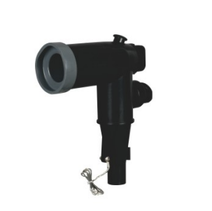
YIEOU’s American cable accessory range includes products such as 200A loadbreak elbow connectors, bushing inserts, casing seats, loadbreak junctions, grounding elbows, insulation caps, and elbow surge arresters for coordinated transformer and distribution-equipment connections.
Internal Cable Connections
Some compact substations use an internal medium-voltage cable between the switchgear and transformer. Although the cable route is short, it may pass through partitions, narrow channels, or areas close to other electrical components.
The connection design should account for:
- Minimum cable bending radius
- Cable support points
- Separation from moving mechanisms
- Distance from heat-producing components
- Phase identification
- Grounding continuity
- Ease of cable replacement
- Access to both connector ends
A short cable should not be assumed to be mechanically simple. In compact equipment, insufficient routing space can make a short, stiff cable more difficult to install than a longer cable in an open substation.
200A Loadbreak or 600A Deadbreak: Which Connection Is More Suitable?
The choice between a 200A loadbreak system and a 600A deadbreak system depends on the equipment design, circuit current, interface type, and required operating method.
Table 1: Comparison of Common Connector Arrangements
| Selection factor | 200A loadbreak arrangement | 600A deadbreak arrangement |
| Typical current class | 200A | 600A or project-specific higher-current class |
| Typical connector form | Elbow connector | T-shaped, front, rear, or deadbreak connector |
| Common equipment position | Transformer, RMU, cable box, sectionalizing point | Switchgear, transformer, main feeder, distribution cabinet |
| Operating category | Specified loadbreak operation with compatible equipment and procedure | Connected or disconnected only when de-energized |
| Equipment interface | Compatible 200A loadbreak interface | Compatible 600A deadbreak interface |
| Installation space | Relatively compact elbow arrangement | Greater assembly depth may be required |
| Supporting accessories | Insert, junction, cap, grounding elbow, arrester | Bushing, plug, cap, busbar, rear connector, arrester |
| Main selection concern | Interface, cable size, operating duty | Current path, interface type, depth, cable routing |
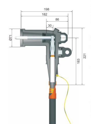
A 200A connector should not be selected simply because it is smaller and easier to install. The circuit’s continuous load current and equipment rating must be suitable.
Similarly, a 600A connector should not be selected merely as a more powerful alternative. It requires a corresponding equipment interface, conductor arrangement, installation space, and deadbreak operating procedure.
The equipment manufacturer should define the intended interface and current class during the RMU or compact substation design stage.
What Information Is Needed Before Model Confirmation?
Accurate Separable Connector selection depends on complete cable and equipment information.
Table 2: RMU and Compact Substation Connector Selection Data
| Required information | Details to provide | Selection purpose |
| System voltage | Nominal and maximum system voltage | Confirms insulation class |
| Circuit current | Continuous current and equipment rating | Confirms current class |
| Connector function | Loadbreak or deadbreak | Confirms operating category |
| Equipment type | RMU, transformer, switchgear, or compact substation | Identifies application position |
| Bushing interface | Drawing, dimensions, standard, and marking | Confirms mechanical compatibility |
| Cable conductor | Copper or aluminum | Determines conductor terminal |
| Conductor size | Cross-sectional area | Matches the conductor connection |
| Insulation diameter | Actual diameter over cable insulation | Matches the connector body or adapter |
| Cable shield | Wire shield, tape shield, or other construction | Confirms grounding arrangement |
| Cable entry | Bottom, side, rear, or top | Affects routing and connector orientation |
| Phase spacing | Center-to-center distance | Confirms installation clearance |
| Cabinet depth | Available connection depth | Determines whether the assembly fits |
| Environment | Indoor, outdoor, humid, dusty, or underground | Affects sealing and protection |
| Accessories | Cap, arrester, grounding elbow, busbar, or junction | Completes the connection system |
The cable model alone may not be sufficient. Cables with the same conductor cross-section can have different insulation diameters, shielding structures, and outer dimensions.
For replacement projects, the existing connector marking, equipment bushing drawing, and clear photographs should be provided. Photographs help identify the general product family, but they should not replace dimensional confirmation.
Which Accessories May Be Required Around the Connector?
A Separable Connector is usually one component within a wider cable accessory arrangement.
Bushing Inserts and Equipment Interfaces
A bushing insert can establish the required loadbreak interface between the equipment bushing well and elbow connector. The insert must match both the equipment-side structure and the connector.
Where an equipment-side interface is manufactured as a separate casing seat or integral bushing, its installation position, fixing structure, creepage path, and connection method should be confirmed during equipment production.
Insulated Protective Caps
Unused compatible interfaces should be protected with correctly rated insulated caps.
A protective cap is not merely a transport cover. Within a suitable connection system, it supports the insulation and environmental protection of an unused energized interface. Its voltage class, current-class interface, and mating dimensions should match the equipment.
Grounding Elbows
A grounding elbow may be included to support controlled cable grounding during maintenance.
Its presence does not replace the required safety procedure. The circuit must still be isolated, tested, and grounded according to the applicable operating rules. The grounding elbow is one part of the complete maintenance arrangement.
Elbow Surge Arresters
An elbow surge arrester may be installed at a compatible connection point to help limit overvoltage reaching the cable or connected equipment.
Whether it is required depends on the network design, insulation coordination, equipment protection strategy, lightning exposure, and switching conditions. It should be selected as part of the project’s surge-protection design rather than added automatically to every connector.
Junctions and Busbars
Loadbreak junctions and insulated busbars can support cable branching, loop-feed arrangements, sectionalizing points, and multi-way distribution.
These accessories are useful where an RMU or compact substation needs:
- Multiple incoming or outgoing cables
- A loop-feed connection
- Cable branching
- A spare connection position
- Transition between connection arrangements
- Future network expansion
The current class and interface of every connection point must remain consistent with the connector system.
What Installation Problems Commonly Occur in Compact Equipment?
Most installation difficulties can be traced to incomplete coordination between the equipment, cable, and connector.
Insufficient Cable Bending Space
A connector may align with the bushing while the cable cannot reach it without excessive bending. This places mechanical stress on the cable and connector.
The cabinet layout should be checked with the actual cable diameter and minimum bending radius, not with a simplified line in the drawing.
Inadequate Phase Spacing
Connector bodies, grounding wires, test points, and rear accessories occupy more space than the bare equipment bushings.
Phase spacing should be evaluated using the complete assembled dimensions. It must also allow installers to clean, lubricate, assemble, torque, inspect, and remove each phase safely.
Incorrect Connector Orientation
An elbow connector may need a particular orientation to align the cable naturally and keep its operating eye accessible.
Rotating the connector into position by forcing the cable can create unwanted mechanical loading. Cable direction and bushing orientation should be coordinated before the cable is cut.
Mixed Interface Components
Using connector bodies, bushings, inserts, caps, or plugs from unverified interface systems may create dimensional and performance uncertainty.
Matching should be confirmed through technical drawings, relevant interface requirements, and manufacturer documentation rather than external appearance alone.
Incomplete Installation Kits
Site delays frequently occur when the connector body arrives without the correct terminal, adapter, probe, screw, grounding component, cleaning material, lubricant, cap, or installation instruction.
Each connection position should have a defined bill of materials. The packaging label should identify the connector model, cable range, equipment interface, phase quantity, and supporting accessories.
How Does Factory Control Support Reliable RMU and Substation Connections?
The connector selected during engineering must remain consistent throughout production.
For molded connector components, critical controls may include:
- Raw-material identification and storage
- Rubber injection conditions
- Epoxy molding conditions
- Insert positioning
- Curing parameters
- Mold maintenance
- Surface inspection
- Functional dimension measurement
- Conductive component verification
- Assembly completeness
- Electrical testing
- Product marking and packaging
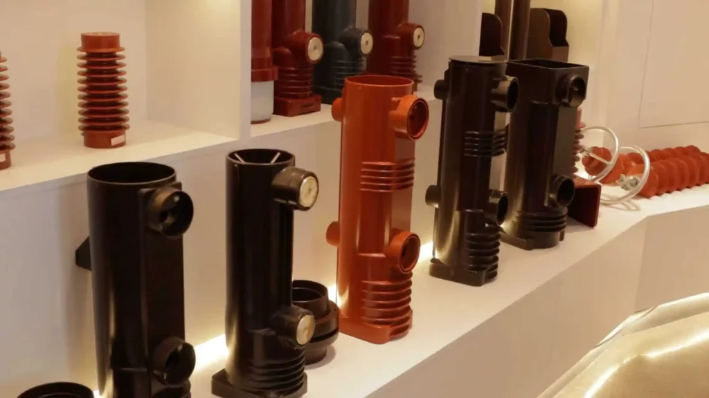
Dimensional consistency is particularly important for RMU and compact-substation projects because several identical cable compartments may be installed in one lineup. Variation between connectors can affect assembly force, cable positioning, and interface fit.
YIEOU’s manufacturing capabilities include automatic rubber injection and epoxy-molding equipment together with material-analysis, voltage-withstand, partial-discharge, and electrical-performance testing facilities. The company’s product range covers cable-side connectors, equipment-side interfaces, grounding accessories, protective components, busbars, and surge-protection products.
By confirming the cable data, bushing interface, cabinet layout, accessory list, labeling, and packaging before production, the factory can maintain a clearer connection configuration across samples, batch orders, and future repeat supply.
How Should an RMU or Compact Substation Connection Be Reviewed?
Before the equipment enters production, the project team should complete a connection review covering four areas.
Electrical review
Confirm the voltage class, continuous current, connector operating category, insulation level, equipment rating, grounding method, and surge-protection arrangement.
Interface review
Confirm the bushing drawing, connector interface, conductor terminal, cable insulation range, accessory dimensions, and applicable technical requirements.
Mechanical review
Confirm cabinet depth, phase spacing, cable bending radius, cable-entry position, connector orientation, mechanical support, and installation-tool access.
Delivery review
Confirm the complete parts list, model marking, phase quantities, installation instructions, packaging groups, spare components, and required test documentation.
This review is especially valuable for repeated RMU panels or standardized compact substations. Once the configuration is confirmed, the same connection arrangement can be maintained across multiple units without repeating basic selection work for every cabinet.
Frequently Asked Questions
Can the same Separable Connector be used in both an RMU and a compact substation?
It may be possible when the system voltage, current class, cable dimensions, equipment bushing, operating category, and installation space are the same. However, each installation position should still be reviewed separately because cabinet layout and cable routing can differ.
Is a 200A elbow connector always suitable for an RMU?
No. Some RMUs use 200A loadbreak interfaces, while others require 600A or 630A deadbreak connector systems. The equipment bushing and circuit rating determine the correct product family.
Can a deadbreak connector be disconnected under load?
No. A deadbreak connector must be operated only after the circuit has been properly de-energized, isolated, tested, and grounded according to the applicable procedure.
Why is the cable insulation diameter required?
The connector body or cable adapter must fit the actual diameter over the cable insulation. Conductor cross-section alone does not confirm this dimension.
Should surge arresters be installed on every compact substation connector?
Not automatically. Surge-arrester requirements depend on the network design, insulation coordination, lightning exposure, switching conditions, and equipment-protection strategy.
Conclusion
A Separable Connector used in a ring main unit or compact substation must satisfy both electrical and mechanical requirements. Correct voltage and current ratings are essential, but the equipment bushing, cable insulation diameter, operating category, phase spacing, cabinet depth, cable bending radius, grounding arrangement, and accessory combination are equally important.
The connector should therefore be selected as part of the complete cable-to-equipment interface. Reviewing the connector body, equipment bushing, conductor terminal, protective cap, grounding accessory, surge arrester, junction, and installation space together helps reduce interface mismatch, incomplete kits, difficult cable routing, and changes at the installation site.
YIEOU manufactures Separable Connector products and related medium-voltage cable accessories for RMUs, compact substations, transformers, switchgear, and cable-distribution equipment. Send us the cable datasheet, equipment-bushing drawing, cabinet dimensions, electrical ratings, and required accessory arrangement. Our team will help confirm a coordinated connection solution for production and project delivery.