
A pad-mounted transformer connects an underground medium-voltage cable network to the local distribution load. Although the transformer enclosure may appear compact from the outside, its primary cable compartment must accommodate the cable entry, equipment bushings, separable connectors, grounding arrangement, surge protection and the operating space required for installation and maintenance.
For many 15kV and 25kV pad-mounted transformer applications, a 200A loadbreak separable connector provides the removable, insulated and screened connection between the underground cable and a compatible transformer interface. However, the elbow connector alone does not define the complete arrangement. The equipment bushing, cable dimensions, circuit layout and supporting accessories must all be coordinated before the connector model is confirmed.
As a manufacturer of medium-voltage cable accessories, YIEOU supplies 200A loadbreak elbow connectors together with bushing inserts, equipment-side interfaces, loadbreak junctions, grounding elbows, insulated protective caps and elbow surge arresters. This allows the transformer connection to be reviewed as one system rather than as several unrelated parts.
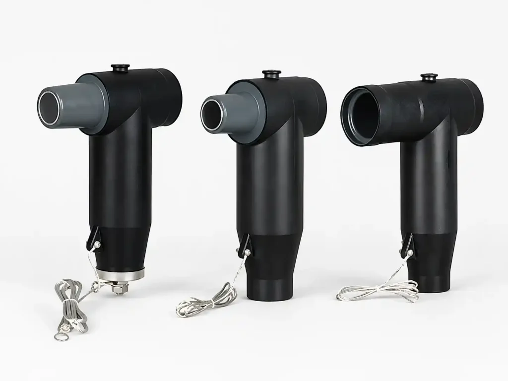
Why Does a Pad-Mounted Transformer Need a Dedicated Connector Configuration?
Pad-mounted transformers are normally installed in outdoor distribution systems where the incoming medium-voltage cables approach the transformer underground. Unlike an overhead transformer connection, the primary cable termination is enclosed inside a locked compartment and must fit within a defined equipment layout.
The connection must perform several functions at the same time:
- Carry the required continuous current
- Maintain insulation across the medium-voltage interface
- Control the electrical field around the cable termination
- Continue the cable shielding and grounding path
- Seal the cable-to-equipment interface
- Allow the circuit to be tested, grounded or reconfigured when required
- Fit within the transformer cable compartment without overstressing the cable
A separable connector supports these functions only when it is matched to a compatible equipment interface. Markings such as “15kV” and “200A” are important, but they do not confirm that two components have the same mechanical interface, cable range or operating category.
Pad-mounted transformer projects also differ in their circuit arrangements. A simple radial-fed transformer does not require the same primary-side layout as a loop-fed unit with incoming and outgoing cables. The number and position of transformer bushings, internal switching arrangement, spare interfaces and maintenance procedure must therefore be understood before the accessory list is prepared.
What Makes Up a Complete 200A Transformer Connection?
A common 200A loadbreak connection begins at the transformer’s primary bushing well or another compatible equipment-side interface. A bushing insert may then be installed to provide the connection surface required by the loadbreak elbow.
On the cable side, the elbow connector contains the conductor connection, insulation structure, electrical stress-control area, external conductive screen, test-point arrangement and grounding provision required by its design.
Typical Connection Sequence
A complete cable-to-transformer path may include:
- Transformer bushing well or equipment-side interface
- Compatible 200A bushing insert
- Loadbreak interface between the insert and elbow
- 200A 负载断开肘形连接器
- Conductor lug or cable connector
- Prepared medium-voltage cable insulation and screen
- 电缆接地组件
- Optional protective, grounding or surge-control accessories
YIEOU’s JY ZT-15/200 is intended for a 15kV 200A loadbreak connection, while the JY ZT-25/200A supports the corresponding 25kV product class. Where the transformer provides a compatible bushing well rather than a finished loadbreak interface, a product such as the JY DTT-15/200 bushing insert may form part of the assembly.
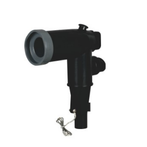
Table 1: Main Components in a 200A Pad-Mounted Transformer Connection
| 组件 | Installation position | 主函数 | Key information to confirm |
|---|---|---|---|
| Transformer bushing well | Transformer equipment side | Provides the base equipment interface | Drawing, voltage class, interface dimensions |
| 衬套 | Installed in a compatible bushing well | Establishes the 200A loadbreak interface | Interface type and compatibility |
| 负荷隔离开关肘型连接器 | Cable side | Connects the shielded cable to the transformer | Voltage, cable range, conductor and operating category |
| Conductor connector | Inside the elbow assembly | Connects the cable conductor electrically | Copper or aluminum conductor and cross-section |
| Grounding components | Cable screen and connector screen | Maintains the grounding and shielding path | Cable screen construction and grounding design |
| 绝缘保护帽 | Unused compatible interface | Insulates and protects a spare connection point | Voltage, current and interface class |
| Grounding elbow | Temporary grounding position | Supports controlled grounding during maintenance | Approved grounding procedure and interface |
| 弯头浪涌抑制器 | Transformer cable interface | Helps limit incoming overvoltage | System protection study and installation position |
| 负载断开连接器 | Separate junction or cabinet position | Supports looping, tapping or sectionalizing | Number of ways and network arrangement |
The exact configuration depends on what the transformer manufacturer includes with the equipment. Some pad-mounted transformers are delivered with the required equipment-side interfaces already installed. Others may require separate bushing inserts or related casing components. The transformer supply scope should therefore be checked before ordering the cable accessories.
How Do Radial-Feed and Loop-Feed Transformers Change the Arrangement?
The primary distribution topology has a direct effect on the number of separable connectors and accessories required.
Radial-Feed Arrangement
A radial-fed transformer receives power from one primary feeder. The transformer is located at the end of that branch, so there is normally no outgoing primary cable continuing the circuit through the transformer position.
A basic radial-feed arrangement may include:
- One primary cable connection per phase
- One compatible transformer interface per phase
- One 200A loadbreak elbow connector per phase
- 电缆屏蔽层和接地组件
- Surge protection where required by the system design
- Insulated caps for any unused compatible interfaces
The relative simplicity of a radial arrangement does not remove the need for interface verification. The cable may still enter from below or from the side, and the enclosure must provide enough room for the elbow body, phase spacing and cable bending radius.
The maintenance strategy should also be considered. If the project requires temporary grounding or cable testing, the equipment layout must provide an appropriate place for those operations. This may involve a grounding elbow, parking position or a separate junction point rather than treating the operating procedure as an afterthought.
Loop-Feed Arrangement
A loop-fed transformer is positioned along a primary distribution loop. One cable may enter from the upstream section while another continues toward the next transformer or distribution point.
Depending on the transformer design, the primary compartment may contain incoming and outgoing bushings, internal switches or other sectionalizing components. The separable connectors connect the cables to the designated equipment interfaces, but they should not be assumed to replace the transformer’s internal switching arrangement.
A loop-feed layout may require:
- Incoming 200A elbow connectors
- Outgoing 200A elbow connectors
- Correct identification of source and load-side cables
- Coordination with the transformer’s internal switches
- Additional space for two cable sets
- Clear phase and circuit labelling
- Grounding provisions for each cable section
- Spare-interface protection where future expansion is planned
Cable routing becomes more demanding in a loop-feed compartment because two primary cable sets may enter the same enclosure. The design must avoid excessive crossing, twisting or bending of the cables. The elbow orientation should allow the cables to approach the bushings naturally rather than forcing the connector to hold the cable in position.
When Is a Separate Junction Needed?
A pad-mounted transformer should not automatically be used as the only network branching point. Where the underground system requires several taps, multiple outgoing feeders or more extensive sectionalizing, a separate cable junction or branch cabinet may provide a clearer distribution structure.
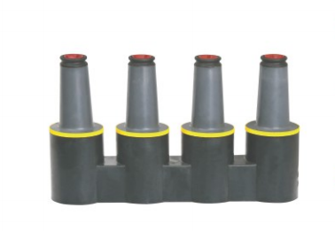
YIEOU’s JY MP-15kV 200A loadbreak junction can be considered where the system needs compatible connection points for looping, tapping, splicing or sectionalizing. Its use should be based on the single-line diagram and network operating plan rather than added only because spare connections may be useful later.
How Should the Voltage Class Be Confirmed?
The connector voltage class must coordinate with the cable system, transformer primary rating and equipment interface.
A system described informally as 10kV, 11kV, 13.8kV or another nominal voltage should not be matched to a connector based only on that nominal number. The project documents should identify the equipment voltage class, maximum system voltage and the accessory requirements used for the transformer interface.
For YIEOU’s 200A loadbreak range, the main distinction is between the 15kV and 25kV product classes. The elbow connector, bushing insert, protective cap, grounding accessory and any related junction must belong to the same compatible connection system.
Mixing components solely because they show the same current rating can result in:
- Incorrect interface engagement
- Inadequate insulation coordination
- Installation difficulty
- Poor sealing pressure
- Uncertain operating performance
- Incomplete accessory matching
The transformer bushing drawing should be treated as a primary selection document. Product photographs may help identify the general connector family, but they cannot reliably show every critical interface dimension.
Why Is Cable Cross-Section Not Enough for Connector Selection?
One of the most common mistakes is selecting a 200A separable connector only from the cable conductor cross-sectional area.
The conductor size is necessary because the internal conductor connector must fit the cable. However, the molded connector body must also fit the actual diameter over the cable insulation.
Two cables with the same conductor cross-section may use different:
- Conductor constructions
- Insulation thicknesses
- Insulation materials
- Metallic screen designs
- Semiconductive screen structures
- Outer sheath thicknesses
- Overall outside diameters
As a result, the cables may not use the same elbow connector range or conductor component.
Information Required from the Cable Datasheet
Before YIEOU confirms the connector configuration, the cable information should include:
- Rated cable voltage
- Copper or aluminum conductor
- 导体横截面积
- Diameter over the conductor
- Diameter over the cable insulation
- Insulation material
- 半导体屏蔽结构
- Metallic screen or shield design
- Outer sheath construction
- Cable manufacturer and model
The diameter over insulation affects the internal fit, stress-control position, sealing pressure and installation force. It should be taken from the cable manufacturer’s datasheet or measured according to the accessory selection requirements.
Nominal conductor size alone should therefore never be used as the final basis for confirming the JY ZT-15/200, JY ZT-25/200A or another elbow connector configuration.
How Do Supporting Accessories Change the Transformer Connection?
The main elbow connector carries the cable to the transformer, but supporting accessories determine how unused interfaces, maintenance operations and overvoltage protection are handled.
Insulated Protective Caps
Any unused compatible interface must be properly insulated, sealed and protected. It should not be left exposed simply because the transformer compartment is locked.
An insulated protective cap can be used on a correctly matched spare interface to:
- Maintain insulation
- Protect the connection surface
- Reduce exposure to dust and moisture
- Prevent accidental contact
- Preserve a future connection point
The cap must match the same interface and voltage class as the equipment connection. It is an electrical accessory, not a general-purpose dust cover.
Grounding Elbows
A grounding elbow provides a visible cable-grounding connection during approved maintenance procedures. In a 200A loadbreak system, a product such as the JY JDZT-15/200 may form part of the project’s grounding arrangement.
Its presence does not replace the required isolation, testing and safety procedure. Before grounding, the circuit must be placed in the correct operating condition and handled by qualified personnel using the approved equipment and sequence.
The transformer layout must also provide a suitable location for the grounding connection. It is not enough to order the grounding elbow without identifying where and how it will be used.
Elbow Surge Arresters
An elbow surge arrester may be installed at a compatible cable-equipment interface to help limit incoming overvoltage. YIEOU’s JY BLQ-17/50 is one of the associated products available for this type of 200A accessory arrangement.
The arrester location should be based on the system protection design. Relevant considerations include:
- Transformer insulation coordination
- Cable length and routing
- Exposure to lightning
- Switching conditions
- Distance from other surge-protection devices
- Grounding conductor path
- Available transformer compartment space
Surge protection should be planned with the complete transformer and cable system. Adding an arrester without checking its electrical rating, grounding arrangement and physical installation position does not create a coordinated protection solution.
Can Every 200A Separable Connector Be Operated Under Load?
No. The word “separable” only means that the connection can be separated under its defined conditions. It does not mean that every separable connector may be disconnected while energized.
A 200A loadbreak elbow is intended for specified loadbreak operation only when:
- The elbow is genuinely rated for loadbreak service
- It is connected to a compatible loadbreak interface
- The circuit conditions remain within the product rating
- The correct operating tools are used
- The equipment instructions are followed
- The required safety procedures are in place
- The operation is carried out by qualified personnel
A deadbreak connector must be de-energized before it is separated. Loadbreak and deadbreak products should therefore never be treated as interchangeable simply because both are removable cable accessories.
The transformer operating plan should clarify whether the elbows will actually be used for switching or whether they are primarily intended to provide a removable connection for de-energized maintenance. This affects connector selection, equipment arrangement, labelling and staff procedures.
How Does the Transformer Compartment Affect Installation?
A connector may be electrically suitable and still be difficult or unsafe to install because of the enclosure layout.
The transformer drawing should be checked for:
- Height of each bushing above the cable-entry point
- 相间距离
- Distance from the bushing to the enclosure wall
- Space in front of the elbow
- 电缆引入方向
- Cable minimum bending radius
- 接地棒的位置
- Location of operating handles and transformer switches
- Space for protective caps or surge arresters
- Access for installation and operating tools
Cable Bending Must Not Load the Connector
Medium-voltage cable can be stiff, particularly when the conductor size, insulation thickness and shield structure increase. If the cable entry is too close to the transformer bushing, the installer may be forced to bend the cable sharply.
This can place continuous mechanical force on:
- The elbow-to-bushing interface
- The conductor connector
- The cable insulation cutback
- The cable screen termination
- The bushing mounted on the transformer
The cable should approach the connector in a controlled curve that respects its permitted bending radius. The elbow should complete the electrical connection, not serve as a mechanical clamp for a poorly routed cable.
Phase Spacing and Elbow Orientation
The operating eye and cable outlet direction should remain accessible. Adjacent elbows must not interfere with each other, the enclosure wall or an installed surge arrester.
For loop-feed transformers, incoming and outgoing cable groups should be arranged so that circuit identification remains clear. The layout should make it difficult to confuse the two cable sections during testing, grounding or replacement.
What Environmental Conditions Should Be Considered?
Pad-mounted transformers are outdoor products, but the internal cable compartment should not automatically be assumed to remain clean and dry throughout its service life.
The project should consider:
- Rainwater entry during installation or maintenance
- Condensation caused by temperature changes
- Humidity inside the enclosure
- Dust and soil contamination
- Insects or small-animal entry
- Corrosive industrial or coastal contaminants
- Temporary water accumulation around cable entries
- Thermal movement of the underground cables
- Mechanical vibration during transport or operation
Connector reliability depends on correct cable preparation, interface cleaning, lubrication where specified, assembly and sealing. A screened molded connector cannot compensate for contamination left on the cable insulation or damage caused during preparation.
Unused interfaces should remain protected, and all accessory surfaces should be stored and handled in a clean condition before installation. Site packaging should also keep each phase set, connector body and related component clearly identified.
What Should Be Confirmed Before Ordering?
The most efficient way to select a 200A separable connector is to review the transformer, cable and circuit arrangement together.
Table 2: Information Required for Configuration Confirmation
| Category | 所需信息 | 为何重要 |
|---|---|---|
| System | Nominal and maximum system voltage | Confirms the connector voltage class |
| Circuit | Radial feed or loop feed | Determines cable and connection quantities |
| 变压器 | Model and primary connection drawing | Identifies the equipment interface |
| 衬套 | Type, rating and dimensional drawing | Confirms connector compatibility |
| 电缆导体 | 铜或铝 | Determines the conductor connector |
| Cable size | 导体横截面积 | Confirms the lug or terminal range |
| Cable insulation | Actual diameter over insulation | Confirms the molded connector fit |
| Cable shield | Shield and screen construction | Determines preparation and grounding |
| Layout | Cable-entry direction and enclosure dimensions | Confirms installation space |
| Operation | Loadbreak or de-energized separation | Defines the operating category |
| Protection | Grounding and surge-protection requirements | Determines supporting accessories |
| Expansion | Spare interfaces or future outgoing cables | Determines caps, junctions and reserved positions |
| Supply | Items included with the transformer | Prevents duplicated or missing accessories |
| Project | Quantity, drawings and labelling requirements | Supports production and site identification |
A single-line diagram is especially useful for loop-feed projects because it shows where the transformer sits in the underground network. The primary compartment drawing then confirms whether the proposed connector arrangement can physically be installed.
What Are the Most Common Configuration Mistakes?
Selecting Only by “15kV 200A”
The voltage and current labels do not prove that the connector and transformer bushing share a compatible interface. The drawings and actual interface system must also match.
Ordering the Elbow Without the Equipment-Side Component
A loadbreak elbow cannot connect directly to every bushing well. A compatible bushing insert or another equipment-side component may still be required.
Ignoring the Diameter Over Cable Insulation
The conductor terminal may fit while the molded connector body does not. Both conductor size and insulation diameter must be confirmed.
Treating Radial and Loop Feed as the Same Layout
Loop-feed transformers normally involve more cables, more connection points and more complex routing. The accessory quantities and compartment requirements must reflect the actual circuit.
Leaving Spare Interfaces Incompletely Protected
An unused interface should receive a correctly rated and compatible insulated cap. An improvised cover does not provide the required electrical protection.
Adding Accessories Without Allocating Space
Grounding elbows, surge arresters and junction arrangements require installation and operating space. The accessory list must be coordinated with the enclosure layout.
Assuming Loadbreak Means Unrestricted Switching
A loadbreak elbow can only be operated under its defined ratings, with a compatible interface, suitable tools and approved procedures. It should not be treated as a general-purpose disconnect.
Forcing the Cable Into Position
Poor cable routing can load the elbow, conductor connection and transformer bushing continuously. The enclosure and cable entry should accommodate the required bend before installation begins.
How Does YIEOU Support Pad-Mounted Transformer Projects?
At YIEOU, a pad-mounted transformer connection is reviewed from both the cable side and the equipment side.
The process can include:
- Reviewing the system voltage and circuit topology
- Checking the transformer bushing drawing
- Matching the cable conductor and insulation dimensions
- Confirming the 15kV or 25kV 200A connector class
- Coordinating the elbow with the required bushing insert
- Identifying caps, grounding elbows, junctions and surge arresters
- Reviewing product quantities for radial or loop-feed arrangements
- Preparing drawings, model labels and grouped packaging
- Maintaining dimensional consistency between samples and batch production
YIEOU’s American cable accessory range includes the JY ZT-15/200 and JY ZT-25/200A loadbreak elbow connector families, together with compatible equipment-side and supporting components. Because these products can be coordinated through the same manufacturing and quality-control system, the project does not need to treat the elbow, insert and protective accessories as unrelated purchases.
常见问题解答
Can one 200A separable connector fit every pad-mounted transformer?
No. The voltage and current ratings may appear correct while the equipment bushing interface, cable insulation diameter or conductor connection remains incompatible. The transformer bushing drawing and cable datasheet must be reviewed.
Is a bushing insert always required?
Not always. Some transformers already include the required compatible interface. Others provide a bushing well that requires a separate insert. The transformer supply scope and equipment drawing determine what must be ordered.
Can the same connector be used for radial-feed and loop-feed transformers?
The same connector family may be suitable when the voltage, cable and interface specifications match. However, a loop-feed transformer normally requires more connectors, different cable routing and coordination with the transformer’s switching arrangement.
Should every spare transformer interface have an insulated cap?
A spare compatible energized interface should be protected with the correctly rated insulated accessory required by the equipment design. It should not remain exposed inside the compartment.
What information should be sent to YIEOU first?
Provide the single-line diagram, transformer primary connection drawing, bushing details, cable datasheet, conductor material, conductor size, diameter over insulation, cable-entry direction and required accessories. These documents provide a much stronger basis for selection than photographs alone.

结论
啊 200A separable connector for a pad-mounted transformer should be selected as part of a complete cable-to-equipment system.
The final configuration depends on whether the transformer is radial-fed or loop-fed, which equipment interface is installed, how the underground cables enter the enclosure and which maintenance or protection accessories are required. Voltage and current markings are only the starting point. Cable insulation diameter, conductor material, bushing compatibility, enclosure dimensions, grounding provisions and operating procedures must also be coordinated.
YIEOU manufactures 15kV and 25kV 200A loadbreak elbow connectors and related medium-voltage cable accessories for pad-mounted transformer and underground distribution applications. Welcome to contact us with your transformer drawings, cable data and circuit arrangement. We will help you confirm a practical separable connector configuration and the corresponding accessory set for your project.