产品概述
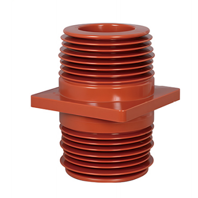
TG3-35Q/260×260×395 3AV3 墙式绝缘子 是一款用于35千伏和40.5千伏高压电力系统的环氧树脂浇注绝缘部件。
它主要用于载流导体(如母线或电缆)穿过开关设备隔板、墙壁、金属面板或其他接地结构的地方。套管提供可靠的电气绝缘和机械支撑,并广泛用于抽出式 switchgearKYN61高压开关柜、变电站和配电设备。
Manufactured using an integrated epoxy resin APG process, the product features an optimized multi-shed structure, excellent electrical insulation, high mechanical strength, and reliable environmental adaptability. It is one of the key insulating components used in 35 kV high-voltage equipment.
技术规格
| 参数 | 规格 |
|---|---|
| 产品型号 | TG3-35Q/260×260×395 3AV3 |
| 额定电压 | 40.5 kV, suitable for 35 kV systems |
| 额定频率 | 15–60 Hz |
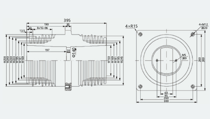
| 法兰尺寸 | 260 × 260 mm |
| 总高度 | 395 mm |
| 材料 | Glass-fibre-reinforced epoxy resin |
| Manufacturing Process | APG casting |
| Insulation Type | Indoor type; outdoor versions available upon request |
| 工频耐压 | ≥95 kV for 1 minute under dry conditions |
| 雷电冲击耐受电压 | ≥185 kV peak |
| 局部放电 | ≤5 pC at 1.1 × Un |
| 热等级 | Class F, long-term operating temperature up to 155°C |
| 阻燃等级 | UL94 V-0 |
| 爬电距离 | ≥1,000 mm, suitable for Pollution Level IV environments |
| 额定电流范围 | 3,150–5,000 A; customizable |
| Seismic Resistance | Suitable for seismic intensity up to Level 8 |
| Structural Type | Unshielded 3AV3 design |
产品特点
Excellent Electrical Insulation
The bushing is manufactured from an epoxy resin matrix reinforced with alkali-free glass fibre. With a volume resistivity above 10¹³ Ω·m and low dielectric loss, it provides reliable insulation against high voltages and helps reduce the risk of electrical breakdown and surface tracking.
The integrated APG moulding process produces a dense and uniform structure with fewer internal bubbles and voids, improving long-term dielectric performance.
Its multi-shed profile increases the creepage distance and improves resistance to pollution flashover, condensation, moisture, and dust accumulation.
高机械强度
The one-piece cast structure provides a flexural strength of at least 300 MPa and reliable resistance to impact, vibration, and installation stress.
It can withstand electrodynamic forces generated by busbars during short-circuit conditions, helping prevent deformation, displacement, and cracking during operation.
The square flange structure ensures secure installation and good compatibility with high-voltage switchgear frames.
强大的环境适应性
The product provides reliable performance across a wide temperature range and is resistant to:
- High and low temperatures
- Electrical and thermal ageing
- Oil contamination
- Acids and alkalis
- Organic solvents
- Moisture and condensation
- Mould and insects
The hydrophobic surface helps reduce moisture adhesion and lowers insulation risks in humid operating environments.
Safe and Reliable Design
The low-partial-discharge structure helps maintain uniform electric field distribution and reduces the risk of accelerated insulation ageing.
The smooth internal and external surfaces contain no sharp edges, helping prevent electric field concentration and corona discharge.
The product is designed to comply with GB/T 11022, GB/T 3906, and other applicable standards. CCC-certified configurations can be provided according to product and project requirements.
The 3AV3 series uses an unshielded design, providing straightforward installation and compatibility with mainstream 35 kV withdrawable switchgear configurations.
应用
The TG3-35Q/260×260×395 3AV3 Wall Bushing is suitable for three-phase AC power systems with rated voltages of 35 kV or 40.5 kV and frequencies from 15 to 60 Hz.
典型应用包括:
- Busbar passage insulation in KYN61 high-voltage switchgear
- Withdrawable high-voltage switchgear
- Switchgear partition and wall penetrations
- Busbar connections between transformers and switchgear
- Substation power distribution equipment
- High-voltage distribution rooms in industrial facilities
- Power plants and utility power distribution systems
- Busbar and conductor insulation support
- 35 kV vacuum circuit breakers
- Disconnectors and isolating switches
- Current transformers and other high-voltage components
操作条件
Standard Operating Environment
| Condition | Requirement |
|---|---|
| 环境温度 | -40°C to +40°C for indoor models |
| Customized Outdoor Temperature | -40°C to +80°C |
| Installation Altitude | ≤1,000 m |
| Monthly Average Relative Humidity | ≤90% at 25°C |
| 冷凝 | Not permitted under normal operating conditions |
| Frost Formation | Not permitted |
| Seismic Intensity | ≤Level 8 |
| 安装位置 | Indoor; outdoor versions available |
| Corrosive or Flammable Gases | Not permitted |
| Severe Dust or Salt Spray | Special configuration required |
| Frequent Severe Vibration | Not permitted |
High-Altitude Conditions
For installations above 1,000 metres, the effects of reduced air insulation and heat dissipation should be considered.
As a general selection reference, the rated current may need to be reduced by approximately 10% for each additional 1,000 metres of altitude. Alternatively, a reinforced high-altitude version can be customized.
The final derating factor should be confirmed according to the complete switchgear design and applicable technical requirements.
Heavily Polluted Environments
For areas exposed to severe dust, salt spray, conductive pollution, or high humidity, the following customized options are available:
- Extended creepage distance
- Additional or enlarged sheds
- RTV anti-pollution flashover coating
- Enhanced sealing structure
- Customized insulation profile
Low-Temperature Conditions
A cold-resistant epoxy resin formulation can be selected to maintain mechanical strength and insulation performance at temperatures down to -40°C.
安装要求
Flange Installation
The flange must fit closely against the switchgear panel, wall, or mounting partition.
All mounting bolts should be tightened evenly according to the specified torque. Uneven or excessive tightening may produce local stress and damage the epoxy resin structure.
Conductor Alignment
The conductive rod or busbar must be installed coaxially with the inner opening of the bushing.
Incorrect alignment may cause mechanical stress, uneven electrical clearances, or electric field distortion.
Do not force an oversized or misaligned conductor through the bushing.
Surface Cleaning
Before installation, clean the bushing surface thoroughly and remove:
- Dust
- Oil
- Moisture
- Metal particles
- Packaging residue
- Other contaminants
The insulating surface must remain clean and dry to maintain reliable dielectric performance.
电气间隙
After installation, check the clearance between the conductor, bushing, grounded metal parts, and adjacent electrical components.
The completed assembly must meet the insulation coordination and minimum electrical clearance requirements of the 35 kV system.
Inspection and Maintenance
Regularly inspect the bushing for:
- Surface cracks
- Electrical tracking marks
- Carbonization
- Contamination accumulation
- Moisture or condensation
- Mechanical deformation
- Loose mounting bolts
- Abnormal partial discharge
- Arc or corona damage
Clean the surface using a dry, soft, lint-free cloth. Do not use abrasive tools, metal brushes, or corrosive solvents.
An insulation preventive test is recommended every three to five years, depending on the operating conditions and maintenance plan. Typical tests may include:
- Power-frequency withstand voltage testing
- Partial discharge measurement
- Insulation resistance testing
- Visual inspection of the insulating surface
Do not hang heavy objects from the bushing or apply additional mechanical loads that are not included in the equipment design.
Stop operation and replace the bushing immediately if severe cracking, electrical tracking, carbonization, deformation, or abnormal partial discharge is detected.
模型描述
| Code | 描述 |
|---|---|
| TG3 | Epoxy resin wall bushing series |
| 35Q | Rated for 35 kV systems; Q indicates indoor configuration |
| 260×260 | Flange mounting dimensions in millimetres |
| 395 | Overall height in millimetres |
| 3AV3 | Unshielded structural configuration for 35 kV withdrawable switchgear |
Selection Recommendations
For rated currents above 5,000 A, a customized version with a larger internal diameter, optimized conductor structure, or integrated shielding can be supplied.
Outdoor installation requires an outdoor-type version, normally identified by the suffix W, together with a suitable weather-resistant shed and rain-protection structure.
For Pollution Level IV or more demanding environments, a model with an extended creepage distance is recommended, such as the TG3-35Q/260×260×450 configuration.