
快速回答
啊 可分离连接器 belongs at a compatible medium-voltage cable interface in a rail transit station’s AC distribution equipment, such as an RMU or an auxiliary transformer. Its job is to join the cable conductor to the equipment while maintaining the specified insulation, shielding and sealing. The equipment bushing, voltage class, circuit duty and actual cable dimensions determine the connection. A station application does not make an otherwise incompatible connector suitable.
For station auxiliary distribution, we manufacture screened European-style front and rear connectors and matching protective accessories. A Separable Connector can provide a compact equipment connection, but it does not perform the switching function of the RMU or make two station supplies independent. These accessories must also be distinguished from traction power connections: an AC distribution product is not automatically suitable for a DC traction circuit or a different railway supply system.
Station auxiliary power gives the connection a clear purpose
A station contains equipment that passengers see, including lighting, escalators and lifts, alongside ventilation, drainage and other services in restricted rooms. Where these loads are supplied through a medium-voltage auxiliary substation, cable accessories sit upstream of the low-voltage equipment. Their immediate application is the incoming or outgoing cable connection at the distribution cabinet or transformer, rather than the individual escalator drive or lighting circuit.
This distinction keeps the Separable Connector choice practical. The Separable Connector carries the duty of its own cable circuit. It is not selected by adding the nameplate currents of low-voltage station loads and treating that total as the current at the medium-voltage interface. The station electrical design establishes the circuit voltage and duty; the accessory then has to fit that circuit and its equipment.
At YIEOU, we manufacture medium-voltage cable accessories for equipment connections, alongside insulation components used in rail transit power distribution. Our screened connector range provides equipment-side connections for compatible RMUs, cable branch boxes and prefabricated substations. The useful question is where a detachable screened interface fits the station equipment, with the cable and enclosure considered together.
The same station may contain several connection arrangements. An incoming ring feeder can have a different cable size and operating duty from the transformer branch. A Separable Connector suitable for one position is therefore not a station-wide specification. Repeating the station name across different circuits does not remove the need to distinguish their interfaces, cable constructions and physical layouts.
The bushing determines which connector family can fit
An equipment bushing defines the mating surface that the cable accessory must engage. That includes the insulating profile, contact arrangement, fixing method and dimensions. A Separable Connector that looks similar from the cabinet door can still have a different internal interface. A nominal current rating alone cannot establish compatibility between the equipment and the cable end.
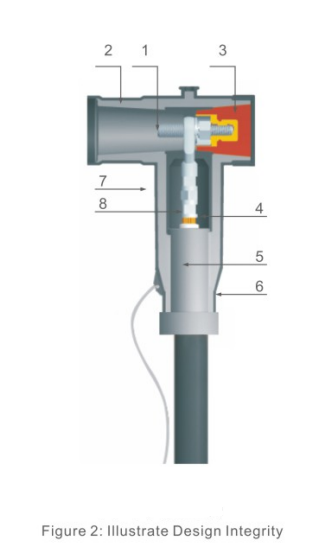
Our European-style 可分离连接器 range includes front connectors intended for the corresponding equipment interface. In a compatible station RMU, the front connector forms the equipment-side cable connection. The rear connector is a different component with a different position in the assembly. Treating the two as interchangeable can produce a layout that cannot be assembled as intended.
For a 10 kV distribution example, our JY JB-15/630A front connector is a screened EPDM product listed for compatible European-style equipment and 10 kV networks. Its stated current rating is 630 A. Those facts identify a relevant product direction; the final fit still depends on the actual bushing and cable configuration. The product name cannot replace the mating dimensions.
An American-style 600 A deadbreak system and a European-style 630 A system remain separate connection systems. The close current values do not make their interfaces equivalent. Similarly, a 200 A loadbreak elbow requires its own matching interface and rated operating conditions. A station maintenance preference cannot turn a fixed deadbreak connection into a loadbreaking device.
Normal and transferred supply duties both affect the connection
Station auxiliary distribution can use alternative supply paths, subject to the project design. A cable circuit may carry one duty during normal operation and a different duty when another section is unavailable. The selected Separable Connector has to suit the highest applicable service condition of its own circuit, together with the cable and equipment ratings.
The Separable Connector continuous current rating describes one part of this requirement. Equipment fault withstand and the assembly’s permitted short-circuit duty also matter. These are separate questions from whether the connector physically fits. Increasing the connector’s nominal current does not improve the fault capability of a cable or bushing that remains unchanged, and it does not establish the capability of the complete station substation.
Consider two transformer branches supplied from a common section of medium-voltage equipment. If the operating arrangement transfers additional load through that section, the common cable connection needs assessment for that operating condition. The relevant current is the medium-voltage circuit duty established by the design, rather than the usual load observed on a quiet day at the station.
We offer different cable accessory families because these positions are not identical. For each Separable Connector assembly, the contact, cable adapter and insulating body work within a defined product configuration. A larger cable conductor or a different connector family may be appropriate when circuit duty changes, but either change also affects cable fit and cabinet space. The connection is assessed as an assembly.
Alternative supplies introduce another limit: their separation depends on the electrical arrangement and switching equipment. Two cables attached at one common connection point are electrically joined there. A detachable cable accessory does not provide the isolation required between supplies, and a second cable connection by itself does not create redundancy.
The station’s operating pattern also influences the conditions around the connection. Ventilation and cooling demand can keep an auxiliary transformer loaded for extended periods, while the electrical room may be warmer than the public concourse. The Separable Connector operates in that equipment environment. Its permissible service conditions need to be considered with the compartment temperature and cable installation, rather than inferred from the temperature passengers experience on the platform.
Cable insulation diameter matters as much as conductor size
Station cable schedules often identify conductors by cross-section, but the rubber interface also engages the cable insulation. Two cables with the same conductor area can have different diameters over insulation because their voltage classes, insulation thicknesses or constructions differ. A Separable Connector must accommodate the actual cable dimensions within the selected accessory’s specified range.
Our JY JB-15/630A front connector product range lists cable cross-sections from 25 to 400 mm², selected according to specification. This is a range across configurations. It does not mean one adapter fits every cable within those limits. The conductor contact has to suit the conductor material and construction, while the cable adapter and stress-control region have to suit the insulation profile.
That becomes especially relevant when a station extension uses a new cable specification beside an earlier installation. Keeping the same conductor area may preserve one design characteristic while changing the diameter that the accessory must seal around. Reusing the earlier adapter designation without checking the replacement cable can leave the physical match unresolved.
The Separable Connector also interfaces with the cable screen and earth connection. The cable’s metallic screen arrangement affects how that connection is completed inside the compartment. The external semiconductive surface and its earthing provisions belong to the installed accessory system; they do not remove the need to connect and support the cable screen correctly.
Cable preparation, crimping and assembly follow the selected product instructions. Dimensions and tightening requirements are specific to the configuration. A general station application discussion cannot supply a universal stripping length or tightening value. We keep these details tied to the accessory supplied, so that an explanation of cable fit does not become an inaccurate installation recipe.
A rear connection changes the available space
Stations can have restricted electrical rooms, with cable trenches, wall clearances and adjacent cabinets limiting access. The visible size of the rubber body is only part of the space required. The assembled connector, cable bend, supports, earthing leads and working access all occupy the compartment. These features determine whether the connection can be installed and later reached without forcing the cable.
For compatible 10 kV distribution arrangements, we offer the JY JBK-15/630A rear connector for use with the corresponding European-style front connection. Its purpose is relevant when the equipment arrangement calls for another cable connection through a compatible assembly. It is not a universal attachment for every front connector with a similar outline or current marking.
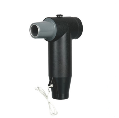
Adding a rear Separable Connector increases the depth and changes where the second cable exits. A compartment that comfortably accepts one cable may lack the clearance for the complete two-cable arrangement. Moving the cable closer to the door can also interfere with access, while forcing a tighter bend can transfer mechanical load to the accessory.
Table 1. Cable connection positions in station auxiliary distribution
| 连接位置 | 产品方向 | Main application limit |
|---|---|---|
| Cable at a compatible RMU bushing | Matching screened front connector | Bushing geometry and complete cable fit |
| Additional cable at a permitted common connection | Compatible front and rear assembly | Shared electrical point, depth and cable routing |
| Unused equipment interface | Rated insulating protective cap | Correct interface, voltage class and earthing |
| Cable at an auxiliary transformer | Accessory matched to its actual bushing | Transformer interface may differ from the RMU |
Cable support therefore belongs near the connection decision. The support arrangement carries the cable’s weight and controls the route into the accessory. A Separable Connector is not a cable support bracket. Allowing a heavy cable to pull sideways on the assembly can compromise the intended fit even when its electrical ratings are appropriate.
A practical layout also leaves the accessory identifiable after installation. Cable labels, earth leads and neighbouring equipment need positions that preserve access to the connection without obstructing the cabinet’s intended operation. During an extension, the working space for a new Separable Connector matters alongside the space occupied in normal service. A drawing that shows only the final rubber bodies can miss the route needed to bring a prepared cable into position.
Shielding and sealing work within the station environment
Underground station rooms can experience moisture, dust and changes in temperature. The specific exposure depends on the room and enclosure. A screened cable connection can help manage the equipment-side insulation arrangement, but the installation still needs suitable environmental control, clean mating surfaces and correctly completed seals. A product protection rating is not permission to ignore water ingress into the cabinet.
Our front and rear EPDM connector products use insulating and semiconductive layers to provide the specified screened connection. The screen requires its intended earth connection. The cable entry and mating surfaces must also be assembled correctly for the sealing arrangement to work. A Separable Connector with an incomplete earth lead or damaged interface is not made acceptable by its outer appearance.
The room environment applies to more than the cable end. Insulators, sensing components and other switchgear parts have their own operating conditions. We manufacture these components as separate product families, with their individual application limits. The moisture resistance stated for one accessory cannot be transferred to every component in the enclosure or used as a cabinet-wide rating.
For any electrical 连接器, the contact interface must remain mechanically and electrically suitable for its duty. At medium voltage, the insulating and screened interfaces add further requirements. Surface contamination, damage or incomplete seating can affect the connection even where the conductor itself has been correctly crimped.
Station refurbishment can disturb nearby cable routes and introduce dust into open compartments. Protecting exposed interfaces during work and restoring the specified enclosure condition are therefore part of preserving the installed assembly. Screened construction does not make live disconnection permissible, and an earthed external surface does not replace isolation and the site’s electrical work procedures.
Our manufacturing and verification facilities include high-voltage and partial-discharge testing capabilities. These checks support the quality of the supplied Separable Connector and its specified insulation system. Field installation remains a separate influence: a tested component still needs the correct cable preparation, mating components and completed earthing arrangement to form the intended connection inside the station equipment.
Spare interfaces need electrical protection from the first stage
Rail transit projects may bring equipment into service in stages. A cabinet position reserved for a later station extension can remain unused while adjacent equipment is operating. Its spare interface needs the specified electrical protection for that condition. A shipping cover or dust cover cannot be assumed to insulate an energised equipment connection.
We offer the JY JYM-630 12 kV European insulation cap for compatible 630 A equipment interfaces, including spare outgoing positions in 10 kV distribution applications. It includes a semiconductive shielding structure and an earthing lead. The 630 A designation identifies the interface family; the cap does not add a new load-carrying feeder or increase the rating of the connection.
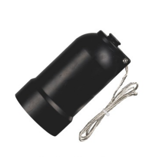
The cap and Separable Connector have different functions in a staged installation. One protects the unused interface in its specified condition; the other completes a cable connection. Replacing a cap with a cable assembly later requires the correct connector and cable configuration, as well as the equipment’s permitted expansion arrangement. An accessible spare position alone does not establish readiness for another circuit.
Test access is another distinct function. A capacitive indication point, where fitted and supported by the selected product, is used with its compatible indication equipment. It is not interchangeable with a high-voltage cable test connection. The installed accessory configuration and equipment instructions establish how testing can be performed without exposing unsuitable components to the test duty.
For station equipment manufacturers and electrical contractors, this separation makes the physical arrangement easier to understand: connected cables, protected spare positions and test provisions each have a defined role. At YIEOU, our 可分离连接器 range supports compatible equipment connections with corresponding accessories, while the station design determines the circuits, protection and switching arrangement.
常见问题解答
Can a Separable Connector be used directly on a DC traction circuit?
An AC distribution connector is not automatically suitable for DC traction service. The voltage system, insulation requirements and equipment interface need a product assessment for that specific application. The station auxiliary AC example here does not establish traction approval.
Does a 630 A Separable Connector fit every station RMU?
No. The bushing geometry, contact arrangement and voltage class must match the selected connector system. A 600 A American-style deadbreak interface and a 630 A European-style interface are not interchangeable simply because their current ratings are close.
Can a rear Separable Connector join two independent supplies?
A compatible front and rear assembly can create a common electrical connection where the equipment arrangement permits it. It does not maintain isolation between the connected cables. Independent supply operation requires the appropriate system arrangement and switching equipment.
Is cable cross-section enough to select a Separable Connector?
No. The actual diameter over insulation, conductor material and construction, cable voltage class and screen arrangement also affect the accessory configuration. A stated Separable Connector conductor range covers product options rather than one universal cable adapter.
Can the connector replace the RMU load switch?
A deadbreak cable accessory does not perform load switching. Its separation requires the appropriate isolated condition and authorised procedure. Loadbreak accessories belong to a matching rated system and also have defined operating limits.
What protects an unused connector interface during staged station work?
A matching insulating protective cap for the 可分离连接器 interface provides the specified electrical protection for the spare interface. The voltage class, interface and earth connection must suit that position. A temporary shipping cover is not a substitute for the required electrical accessory.