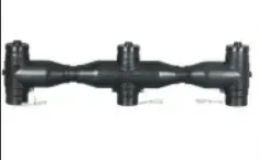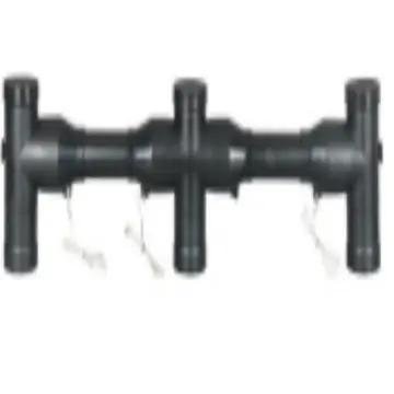
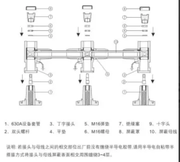
This illustration shows a top bus bar system composed of fully shielded separable cable connectors, representing a typical application for multi-circuit cable connections in European-type ring main units, pad-mounted substations, and similar power distribution equipment.
System Overview
Top Busbar System is assembled by interconnecting multiple European-type cable front connectors and rear connectors through standardized interfaces in series, forming a continuous, fully insulated bus bar channel capable of simultaneously connecting multiple outgoing circuits. It replaces conventional exposed copper bus bars, achieving full insulation, full enclosure, and touch-safe operation of internal bus bar conductors in power distribution equipment, significantly enhancing operational safety and reliability.
System Configuration and Operating Principle
Core Components
European-type front/rear connectors: Integrally injection-molded from EPDM (ethylene propylene diene monomer) rubber with built-in semiconductive shielding layers, rated to IP67 protection, serving as the fundamental units of the bus bar system.
Connecting bus bar: Multiple connectors are linked in series via plug-in connections between adjacent connectors, forming a continuous conductive path.
Grounding device: The grounding leads at the base of the connectors, as shown in the illustration, connect the semiconductive layer on the connector surface to ground potential, placing the connector housing at earth potential and achieving touch-safe operation.
Operating Principle
Conductive connection: Cable conductors are electrically connected through the internal conductive components of the connectors; current is transmitted along the series-connected connector channel to provide parallel power supply across multiple circuits.
Electric field control: The built-in semiconductive shielding layers within the connectors uniformly distribute the electric field, preventing partial discharge caused by electric field concentration and ensuring insulation integrity.
Protection and safety: The fully sealed structure prevents ingress of moisture and dust; IP67 protection enables operation in harsh environments including high humidity and heavy dust; with the connector housing grounded, maintenance personnel face no risk of electric shock upon contact.
System Characteristics and Advantages
| Characteristic | Advantage Description |
|---|---|
| Full insulation and full enclosure | No exposed live parts; touch-safe after housing is grounded, eliminating electric shock hazards; IP67 protection rating provides resistance to moisture, dust, and corrosion |
| Modular design | Standardized connector units allow flexible expansion based on circuit quantity; easy installation with no field casting or welding required |
| High reliability | Integral injection molding process produces a seamless, void-free structure with no risk of long-term aging or cracking; service life exceeding 20 years |
| Safe operation and maintenance | Grounded connector housing allows direct contact by maintenance personnel; no exposed bus bars, eliminating short-circuit faults caused by small animals or foreign objects |
| Space optimization | Compact structure with minimal footprint, compatible with the confined interior spaces of ring main units and pad-mounted substations |
Typical Application Scenarios
Internal bus bar in European-type ring main units: Replaces conventional copper bus bars to achieve fully insulated connections for multiple outgoing circuits; widely used in 10 kV, 20 kV, and 35 kV ring main units.
Bus bar system in pad-mounted substations: Multi-circuit connections on the high-voltage side within pad-mounted substations; compatible with the harsh operating environments of both indoor and outdoor pad-mounted substations.
Cable junction box bus bar: Multi-circuit tapping within cable junction boxes, enabling parallel power supply for multiple cables without the need for additional cable trays or bus bar bridges.
Power distribution systems in industrial and mining enterprises: Bus bar connections for power distribution equipment in humid, dusty, and corrosive environments, enhancing the system’s resistance to contamination and corrosion.
Installation and Maintenance Guidelines
Installation Guidelines
Strip the cable in accordance with process requirements, ensuring that stripped lengths and dimensions conform to connector specifications to avoid damage to the cable insulation.
Clean the interface before connector installation, apply silicone grease evenly, and ensure the connector is fully seated with a reliable, secure connection free of looseness or misalignment.
Grounding leads must be reliably earthed to ensure the connector housing is maintained at ground potential, achieving touch-safe operation.
After installation, inspect the connector sealing surfaces to confirm no gaps or damage, ensuring IP67 protection performance is maintained.
Maintenance Guidelines
Periodically inspect the external condition of connectors for cracks, damage, discharge marks, or contamination buildup, and verify that connections are tight and free of looseness.
Periodically test insulation resistance and contact resistance of connectors to confirm performance meets requirements and to identify potential faults in a timely manner.
Clean connector surfaces to remove accumulated dust and contamination; prevent oil and chemical substances from corroding the rubber connector housing.
When abnormalities such as cracks, physical damage, discharge, or insulation resistance exceeding permissible limits are detected, the affected connectors must be replaced promptly; continued operation with known defects is strictly prohibited.
Applicable Standards and Certifications
International standard: IEC 60840, Test methods and requirements for power cables with extruded insulation and their accessories for rated voltages above 30 kV (Um = 36 kV) up to 150 kV (Um = 170 kV)
National standards: GB/T 12706, Power cables with extruded insulation and their accessories for rated voltages from 1 kV (Um = 1.2 kV) up to 35 kV (Um = 40.5 kV); GB/T 11022, Common specifications for high-voltage switchgear and controlgear standards
All system components have passed type tests conducted by the National Wire and Cable Quality Supervision and Inspection Center and comply with national electric power industry standards.
Appendix: Product Outline Diagram