JDZ12A-10R Voltage Transformer
Product Overview
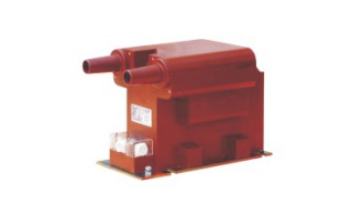
The JDZ12A-10R voltage transformer is a fully-enclosed, epoxy-resin cast, dry-type voltage transformer designed specifically for 10kV (Um=12kV) indoor AC power systems. It incorporates an integrated fuse design that combines voltage transformation, electrical isolation, and overcurrent protection functions. It is primarily used for voltage measurement, energy metering, relay protection, and insulation monitoring in indoor medium-voltage switchgear, and is widely applied in 10kV distribution systems, compact substations, switching stations, and similar installations, meeting the requirements of compact switchgear designs.
Key Product Features
Insulation and Electrical Performance
Fully-Enclosed Epoxy Resin Cast Insulation: The unit is integrally formed by vacuum epoxy resin casting with no internal voids, providing excellent insulation performance. It withstands the 12kV system operating voltage and power-frequency and impulse withstand voltage tests. Partial discharge level ≤10pC. Long-term operation presents no insulation aging risk, with no leakage or oil contamination hazard, suitable for oil-free indoor distribution environments.
Integrated Fuse Protection: A built-in high-voltage fuse enables rapid interruption upon primary-side overcurrent or short circuit, protecting the transformer body from damage. This simplifies the primary circuit design within the panel, reduces the need for external fuse components, and lowers equipment cost and installation space requirements.
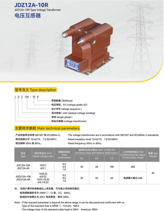
Wide Voltage Ratio Compatibility: Supports standard voltage ratios (e.g., 10/0.1kV, 10/0.1/0.1kV). Metering-class accuracy up to Class 0.2; protection-class accuracy customizable to 3P/6P, meeting requirements for metering, protection, and insulation monitoring applications.
Low Partial Discharge Design: Advanced casting technology keeps partial discharge level ≤10pC, preventing insulation aging caused by long-term partial discharge and improving long-term operational reliability.
Structural and Installation Features
Fully-Enclosed Dry-Type Construction: Integrally cast with no exposed live parts. Protection degree IP20. Oil-free design eliminates fire hazards. Compact and small in volume, compatible with standard 10kV switchgear installation dimensions.
Integrated Fuse Design: High-voltage side incorporates a replaceable fuse assembly requiring no additional fuse mounting brackets, reducing the number of components inside the panel and improving internal space utilization.
Clear Secondary Terminals: Secondary terminals are protected by a terminal cover, clearly labeled, and easy to wire, preventing misconnection and short circuits. Terminal layout conforms to secondary circuit wiring standards for switchgear.
Flexible Mounting: Bottom metal mounting base with fixing holes supports bolt-mounted installation. Suitable for horizontal indoor panel mounting. Provides secure fastening with excellent vibration resistance and facilitates compact arrangement within the panel.
Operational and Maintenance Features
Maintenance-Free Operation: Dry, oil-free construction with no leakage or fire hazard. The epoxy resin cast body offers high mechanical strength, impact resistance, and aging resistance, enabling long-term maintenance-free operation and reduced operating costs. Fuse replacement is straightforward and requires no specialized tools, ensuring high maintenance efficiency.
Wide Temperature Operation: Suitable for ambient temperatures from -30°C to +70°C. Epoxy resin maintains stable performance at both high and low temperatures with no risk of embrittlement or deformation, adaptable to climatic conditions across different regions.
High-Reliability Design: The core is laminated from high-quality silicon steel sheets; windings are wound with enameled copper wire. Low operating losses and minimal heat generation. Capable of withstanding system switching overvoltages and lightning impulse overvoltages. The fuse performs reliably, ensuring dependable protective operation and safe equipment operation.
Technical Parameters (Typical Specifications)
| Parameter Category | Item | Technical Specification |
| Electrical Parameters | System Voltage | 10kV AC (Um=12kV) |
| | Rated Frequency | 50Hz | |
| | Rated Primary Voltage | 10kV | |
| | Rated Secondary Voltage | 100V (metering / protection); 100/3V (insulation monitoring, optional) | |
| | Metering Class Accuracy | Class 0.2 / 0.5 / 1 | |
| | Protection Class Accuracy | 3P / 6P | |
| | Power-Frequency Withstand Voltage (HV terminal) | 42kV / 1min, no breakdown | |
| | Impulse Withstand Voltage (peak) | 75kV, no breakdown | |
| | Partial Discharge Level | ≤10pC | |
| | Insulation Resistance (HV to LV and ground) | ≥1000MΩ | |
| | Built-in Fuse Rated Current | 0.5A (standard), customizable | |
| Structural and Material Parameters | Insulating Medium | Full epoxy resin cast |
| | Protection Degree | IP20 | |
| | Mounting Method | Indoor post-type bolt mounting | |
| | Insulation Thermal Class | Class B (130°C) | |
| Environmental Parameters | Applicable Altitude | ≤2000m (high-altitude customization available) |
| | Operating Ambient Temperature | -30°C to +70°C | |
| | Storage Ambient Temperature | -40°C to +85°C | |
| | Relative Humidity | ≤95% (non-condensing) | |
| Applicable Standards | National Standards | GB 1207 Voltage Transformers; GB/T 20840 series; GB 15166.2 AC High-Voltage Fuses |
Application Scope
Applicable Voltage Level: 10kV (Um=12kV) indoor AC power systems.
Typical Application Scenarios:
Voltage measurement, energy metering, and relay protection in indoor medium-voltage switchgear (KYN28 series) and compact substations;
10kV distribution systems in distribution substations, industrial and mining enterprises, commercial buildings, and industrial parks;
Voltage monitoring, control, and protection signal acquisition in power automation systems;
Compact switchgear applications requiring simplified primary circuits and reduced component count.
Functional Purpose: Steps down high voltage in the power system proportionally to a standard low voltage (100V), providing voltage signals to metering instruments, protective relays, and control equipment while achieving electrical isolation between the primary and secondary systems. The built-in fuse provides rapid interruption upon primary-side overcurrent or short circuit, protecting the transformer body from damage and providing dual assurance for safe equipment operation.
Operating Conditions
Normal Operating Conditions
Altitude: ≤2000m
Ambient Temperature: -30°C to +70°C, without severe temperature fluctuations
Relative Humidity: ≤95% (non-condensing)
Environmental Conditions: Free from corrosive gases, flammable or explosive media, severe vibration and shock, and significant dust or salt fog
Mounting: Indoor post-type installation; avoid direct sunlight, rain, and condensation
Special Operating Conditions (Customization Required)
Altitude exceeding 2000m;
Ambient temperature outside the range of -30°C to +70°C;
Severely polluted, salt-fog, or chemically corrosive environments;
Conditions of heavy vibration or strong impact;
Non-standard voltage ratios, accuracy classes, or fuse parameter requirements.
Installation and Maintenance
Installation Requirements
Pre-Installation Preparation: Inspect the voltage transformer’s appearance — the cast body shall be free of cracks, voids, and damage; terminals shall be clearly labeled and all accessories present. Verify that the model, specifications, voltage ratio, and fuse parameters match the design requirements, and confirm the fuse is intact.
Mechanical Installation: Position the voltage transformer at the designated location inside the switchgear panel. Secure with bolts through the bottom mounting holes, ensuring firm installation with no looseness or misalignment. The mounting surface shall be level to avoid uneven loading.
High-Voltage Side Wiring: Connect the high-voltage terminals per design requirements, ensuring tight connections and good contact. Maintain adequate safety clearance between high-voltage leads and grounded parts or other live components to prevent flashover.
Low-Voltage Side Wiring: Connect the low-voltage terminals according to their labels, with separate wiring for metering, protection, and insulation monitoring circuits; verify correct connections. Secondary circuits must not be short-circuited and must be reliably grounded (single-end grounding) to prevent overvoltages.
Insulation Testing: After installation, measure the insulation resistance of the voltage transformer (HV to LV and ground; LV to ground) to verify insulation performance meets requirements. Check that secondary circuit wiring is correct with no short circuits or open circuits.
Maintenance Guidelines
Regularly inspect the voltage transformer’s appearance: the cast body shall show no cracks, damage, or discharge marks; high-voltage terminals shall show no looseness or oxidation; the fuse shall show no signs of operation or damage.
Regularly inspect high- and low-voltage connections for tightness and absence of heat discoloration. Verify that low-voltage circuit grounding is reliable with no risk of short circuit or open circuit.
Periodically test insulation resistance and voltage ratio to confirm that metering and protection accuracy meets requirements, and check the fuse condition.
Clean dust and contamination from the transformer surface; prevent oil or corrosive substances from adhering; keep the unit dry and clean.
When a fuse operates or is damaged, immediately de-energize and replace it with a fuse of the same type and rating. The use of non-specified fuse types is strictly prohibited. If the voltage transformer exhibits abnormalities such as cracking, discharge, overheating, or voltage ratio deviation, immediately de-energize for inspection; replace the unit if necessary. Operation with known defects is strictly prohibited.
Precautions
Secondary windings must not be short-circuited. A short circuit in the secondary circuit during operation will produce large currents, endangering equipment and personnel safety. During maintenance, the secondary circuit must be reliably open-circuited and grounded.
During installation, avoid impact or collision with the cast body and high-voltage terminals to prevent cracking of the epoxy resin and insulation damage, which would impair insulation performance.
High-voltage side connections must use dedicated insulated conductors, maintaining adequate safety clearance from grounded parts and other live components to prevent phase-to-phase or phase-to-ground discharge.
Equipment grounding must be reliable. The base grounding terminal must be securely connected to the panel grounding busbar.
During storage, keep the unit in a dry, ventilated, cool environment away from direct sunlight, high temperatures, moisture, and mechanical compression to prevent aging or deformation of the cast body and moisture damage to the fuse.
Installation, commissioning, and maintenance must be performed by qualified electrical personnel in strict accordance with electrical safety operating procedures. Fuse replacement must be performed with the equipment de-energized. Live replacement is strictly prohibited.
Standard Configuration List
| No. | Item | Purpose |
|---|---|---|
| 1 | JDZ12A-10R Voltage Transformer Body | Core unit implementing voltage transformation, isolation, and protection |
| 2 | Mounting Bolts and Washers | Used for securing the voltage transformer |
| 3 | Secondary Terminal Cover | Protects low-voltage terminals against misconnection and short circuits |
| 4 | Product Manual | Installation, operation, and maintenance guide including fuse replacement instructions |
| 5 | Product Certificate of Conformity and Factory Test Report | Product quality and performance documentation including voltage ratio and error test data |
| 6 | Spare Fuse (optional) | For replacement upon fuse failure |
Applicable Standards and Certifications
The product conforms to the following national standards: GB 1207 Voltage Transformers; GB/T 20840.1 Instrument Transformers — Part 1: General Requirements; GB/T 20840.3 Instrument Transformers — Part 3: Additional Requirements for Inductive Voltage Transformers; GB 15166.2 AC High-Voltage Fuses. The product has passed type tests and its performance meets the operational requirements of 10kV indoor power systems.
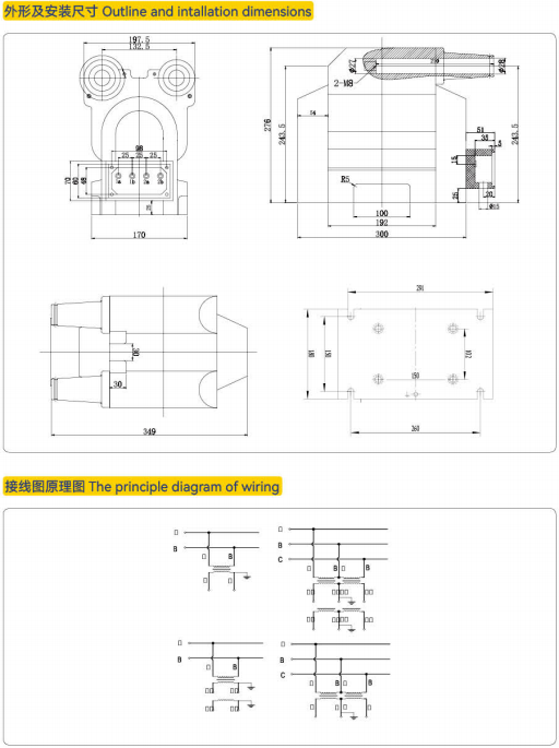
Appendix: Product Outline Drawing