
A separable connector provides an insulated, screened, and removable connection between a medium-voltage cable and equipment such as a transformer, switchgear cabinet, ring main unit, or cable branch box. However, selecting the connector only by voltage class or rated current is not enough.
The cable construction, equipment bushing interface, operating method, installation space, grounding arrangement, and surrounding environment must all be checked together. A 15kV 200A connector may appear suitable on paper but still fail to fit the cable insulation diameter, bushing insert, cabinet layout, or required accessory arrangement.
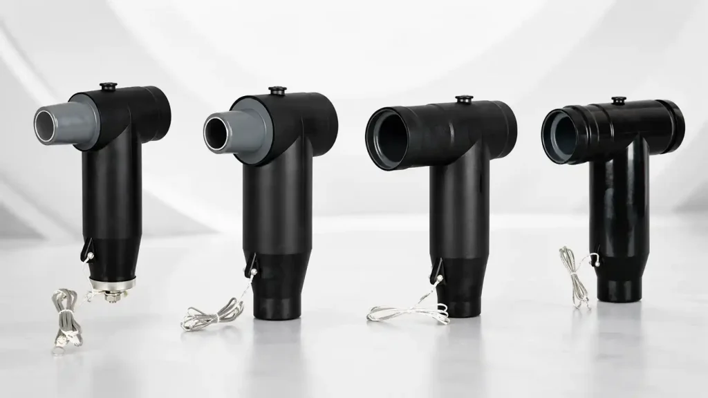
For transformer and switchgear projects, the most reliable approach is to treat the separable connector as part of a complete cable-to-equipment connection system. YIEOU manufactures American cable accessories including loadbreak elbow connectors, bushing inserts, casing seats, loadbreak junctions, grounding elbows, insulation caps, and elbow surge arresters for coordinated medium-voltage connections.
What Information Is Required Before Selecting a Separable Connector?
Accurate selection starts with complete project information. A product model should not be confirmed until both the cable side and the equipment side have been checked.
The following information should normally be provided:
| Selection information | What should be confirmed | Why it matters |
| System voltage | Nominal voltage and equipment voltage class | Determines the required insulation class |
| Continuous current | Circuit operating current and connector rating | Prevents current-rating mismatch |
| Equipment type | Transformer, switchgear, RMU, cable box, or junction cabinet | Helps determine the connection arrangement |
| Equipment interface | Bushing well, bushing insert, casing seat, or other interface | Ensures mechanical and electrical compatibility |
| Cable conductor | Copper or aluminum | Affects conductor connector selection |
| Conductor size | Cable cross-sectional area | Determines the conductor contact component |
| Cable insulation diameter | Actual diameter over cable insulation | Determines whether the connector body fits correctly |
| Cable shield construction | Wire shield, tape shield, or other design | Affects grounding and screen continuity |
| Operating requirement | Loadbreak, deadbreak, or fixed connection | Determines how the connection may be operated |
| Installation environment | Indoor, outdoor, underground, humid, or exposed | Influences sealing and protection requirements |
| Cable entry direction | Top, bottom, side, straight, or angled | Affects elbow orientation and installation space |
| Additional accessories | Grounding elbow, cap, arrester, or junction | Determines the complete accessory combination |
The cable insulation diameter is particularly important. Two cables with the same conductor cross-section may have different insulation thicknesses and outside dimensions. Selecting only by conductor size can therefore lead to an incorrect fit between the cable and the connector body.
Equipment information is equally important. The transformer or switchgear drawing should identify the bushing structure, current rating, voltage class, interface dimensions, number of connection points, and cable-entry direction. When these details are unavailable, photographs alone are rarely sufficient for final model confirmation.
How Do Transformer and Switchgear Connections Differ?
Transformers and switchgear can use similar separable connector components, but the installation conditions are not always the same.
Transformer connections
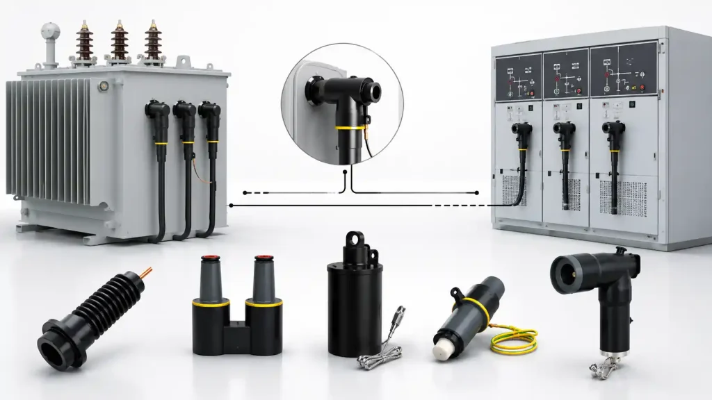
Pad-mounted transformers, compact substations, and distribution transformers commonly provide equipment-side bushings or bushing wells for cable connection. In a typical 200A American-style arrangement, a loadbreak elbow connector may connect to a compatible bushing insert installed in the transformer bushing well.
Transformer connections may also require:
- An insulation cap for an unused energized interface
- A grounding elbow for maintenance procedures
- An elbow surge arrester for overvoltage protection
- A junction for cable branching or sectionalizing
- A parking stand or operating accessory, depending on the equipment design
The position of the transformer bushing should be checked carefully. Limited spacing between phases, enclosure walls, and cable compartments can affect elbow installation and cable bending.
Switchgear connections
Switchgear and ring main units often have more restricted internal space. Cable entry may be from the bottom, and several phases may be arranged close together. The connector must therefore match not only the electrical interface but also the available installation envelope.
Important switchgear considerations include:
- Distance between phases
- Clearance from the cabinet wall
- Cable bending radius
- Orientation of the operating eye
- Accessibility for installation tools
- Position of grounding points
- Space for test points or surge protection accessories
Separable connectors are widely used to connect polymeric cables to switchgear and transformers, but product families may use different bushing types, current ratings, and interface systems. The equipment drawing must therefore be treated as a primary selection document rather than assuming that connectors with similar external shapes are interchangeable.
Which Seven Factors Determine the Correct Separable Connector?
1. Match the voltage class
The separable connector voltage class must coordinate with the cable system and equipment insulation level. The nominal system voltage alone may not provide enough information, so the maximum system voltage and equipment designation should also be checked.
A 15kV accessory should not automatically be used for every network described informally as “10kV” or “11kV.” Local system conventions, equipment specifications, and applicable standards may classify products differently.
For YIEOU’s American cable accessory range, products such as the JY ZT-15/200 and JY ZT-25/200A loadbreak elbow connectors are identified by their respective voltage and current classes. The related bushing inserts, casing seats, junctions, caps, and grounding accessories must be selected for the same connection system.
2. Confirm the continuous current and operating function
Rated current indicates the connector’s continuous carrying capability, but it does not independently define how the connector can be operated.
A loadbreak connector is designed for load switching only when it is installed with the correct loadbreak interface and operated according to the applicable equipment and safety procedures. A deadbreak connector must not be separated while the circuit is energized.
In IEEE-style medium-voltage systems, 200A loadbreak elbows are commonly available for 15kV and 25kV applications, while higher-current deadbreak arrangements often use T-body connector structures. These examples illustrate why current rating and operating type must be checked as separate selection items.
| Connector type | Typical operating principle | Main selection concern |
| Loadbreak connector | Designed for specified switching operations with a compatible loadbreak interface | Confirm switching rating, interface, operating tool, and procedure |
| Deadbreak connector | Connected or disconnected only after de-energization | Confirm de-energized maintenance procedure and interface type |
| Fixed termination | Not intended for routine plug-in separation | Confirm bolted connection and equipment termination design |
The term “separable” does not mean that every connector can be unplugged under load.
3. Match the equipment bushing interface
The equipment interface is one of the most common causes of ordering errors.
The project team should confirm:
- Bushing type
- Interface dimensions
- Rated voltage
- Rated current
- Manufacturer drawing
- Applicable interface standard
- Whether a separate bushing insert is required
For example, YIEOU’s JY ZT-15/200 15kV 200A loadbreak elbow connector may be used with a suitable 200A equipment interface. Depending on the equipment design, the assembly may include a JY DTT-15/200 bushing insert or a compatible casing seat.
A separable connector and bushing should never be matched only because both are marked “15kV 200A.” Their actual interface structures must correspond.
4. Confirm the cable conductor and insulation dimensions
The conductor connector must match the cable conductor material and cross-sectional area. Copper and aluminum conductors may require different connection arrangements or approved conductor components.
The separable connector body must also match the diameter over the cable insulation. This dimension affects:
- Internal fit
- Electrical stress control
- Sealing pressure
- Installation force
- Long-term interface stability
The most useful cable information is usually the manufacturer’s cable datasheet. When that is unavailable, the cable should be measured according to the accessory supplier’s instructions rather than relying on nominal cable size alone.
5. Check shielding and grounding requirements
A screened separable connector should maintain a controlled electrical interface from the cable screen to the equipment grounding system. The cable screen construction and grounding method must therefore be known before the accessory set is finalized.
Depending on the cable and connector design, the installation may involve:
- Grounding braid or grounding wire
- Cable shield connection
- Semiconductive screen continuity
- Grounding eye or grounding point
- Grounding elbow for maintenance
- Test point grounding arrangements
The connector itself cannot correct an incomplete grounding design. Grounding provisions should be coordinated with the cable specification, equipment manufacturer’s instructions, and the project’s safety procedures.
6. Consider the environment and sealing conditions
Transformer and switchgear cable compartments may be installed indoors, outdoors, underground, or in areas exposed to humidity, condensation, dust, or temporary water accumulation.
Environmental questions should include:
- Is the connector installed inside a sealed cabinet?
- Can condensation form in the cable compartment?
- Is the installation below ground level?
- Is temporary flooding possible?
- Will the connector be exposed to direct sunlight?
- Are there corrosive contaminants?
- Will the cable move because of thermal cycling or mechanical vibration?
A screened and sealed connector can support reliable service only when the cable preparation, interface cleaning, assembly, and sealing steps are completed correctly. Environmental suitability should be confirmed from the actual product specification rather than inferred from appearance.
7. Select the full accessory arrangement
The main elbow connector may represent only one part of the final assembly.
A transformer or switchgear connection may also require:
- Bushing insert
- Casing seat
- Insulation cap
- Grounding elbow
- Loadbreak junction
- Surge arrester
- Connecting plug
- Operating rod
- Cable grounding components
Ordering the elbow without confirming the surrounding accessories can result in an incomplete installation kit.
For YIEOU’s 15kV and 24kV American cable accessory range, related components can be selected as a coordinated group. This makes it easier to confirm interfaces, model identification, packaging, and quantities before production.
How Should a Transformer Connection Be Configured?
A common transformer connection begins with the transformer’s equipment-side bushing or bushing well.
For a 15kV 200A loadbreak arrangement, the connection may include:
- Transformer bushing well or equipment interface
- Compatible bushing insert
- 15kV 200A loadbreak elbow connector
- Cable conductor connector
- Cable screen and grounding components
- Optional insulation cap, grounding elbow, junction, or surge arrester
The exact assembly depends on the transformer design. Some equipment already includes the required interface, while other designs require a separate insert or casing component.
The cable compartment must provide enough space for the elbow and the cable’s minimum bending radius. Forcing the cable into position can place mechanical stress on the connector interface and conductor connection. Cable routing should therefore be considered during transformer enclosure design, not only during installation.
Where surge protection is required, an elbow surge arrester may be incorporated into the accessory arrangement. Where a connection point is temporarily unused, a correctly rated insulated cap should be used rather than leaving the interface exposed.
YIEOU’s American cable accessory range includes products for these related functions, allowing the transformer connection to be reviewed as one coordinated assembly rather than as several unrelated components.
How Should a Switchgear Connection Be Configured?
Switchgear selection begins with the cabinet’s cable-entry and bushing drawings.
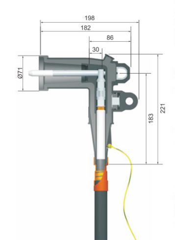
The following dimensions should be checked before confirming the connector:
- Height from the cable entry plate to the bushing
- Horizontal distance between phases
- Distance between the bushing and cabinet wall
- Available space in front of the connection point
- Cable bend radius
- Position of grounding bars
- Direction of the connector operating eye
- Space required for installation and removal
In a compact cabinet, a connector may be electrically compatible but mechanically difficult to install. Cable stiffness becomes especially important when larger conductors enter from below and must turn within a limited compartment.
The project should also confirm whether the switchgear connection is intended for:
- Incoming cable
- Outgoing feeder
- Transformer feeder
- Ring-network connection
- Cable branching
- Temporary grounding
- Surge protection
These functions may require different accessory combinations. A loadbreak junction, for example, can provide multiple connection points for branching or sectionalizing, while a grounding elbow supports a controlled grounding arrangement during maintenance.
The final selection should therefore be based on the switchgear single-line diagram, cable schedule, bushing drawing, and internal layout drawing together.
What Are the Most Common Separable Connector Selection Errors?
Several recurring mistakes can be prevented before the order is placed.
| Common error | Possible result | Recommended action |
| Selecting only by nominal voltage | Incorrect insulation or interface class | Check full system and equipment voltage data |
| Selecting only by cable cross-section | Connector body may not fit the insulation diameter | Confirm conductor size and diameter over insulation |
| Assuming all 200A interfaces are identical | Mechanical mismatch at the equipment connection | Compare bushing and connector drawings |
| Confusing loadbreak with deadbreak | Unsafe operating assumptions | Confirm the operating category explicitly |
| Ignoring conductor material | Incorrect conductor connector selection | State copper or aluminum clearly |
| Ordering only the elbow body | Missing insert, cap, grounding, or connection components | Prepare a complete accessory list |
| Ignoring cabinet dimensions | Insufficient installation or cable-bending space | Review the equipment layout before ordering |
| Using photographs as the only reference | Hidden interface details may be missed | Provide drawings, markings, and dimensions |
| Mixing unverified components | Interface and performance uncertainty | Confirm compatibility as a complete system |
| Failing to identify each kit | Installation delays and site confusion | Use clear labels and grouped packaging |
Many selection problems are not caused by complex electrical calculations. They result from incomplete information being transferred between the cable supplier, equipment manufacturer, accessory factory, contractor, and project team.
A structured selection sheet can reduce these errors significantly.
What Should Be Sent to YIEOU for Model Confirmation?
To confirm a separable connector efficiently, provide as many of the following documents as possible:
- System voltage and frequency
- Required continuous current
- Transformer or switchgear model
- Equipment bushing drawing
- Photograph of the equipment interface
- Cable manufacturer and cable model
- Conductor material
- Conductor cross-sectional area
- Diameter over conductor
- Diameter over cable insulation
- Cable screen construction
- Indoor or outdoor installation
- Cable-entry direction
- Number of phases and connection points
- Required operating function
- Additional accessories
- Project quantity
- Required drawings, labels, or packaging
When existing accessories are being replaced, the original product marking and complete dimensional drawing should also be provided. A photograph can help identify the general product family, but measurements and technical data are still required for final confirmation.
YIEOU combines product selection support with factory-based manufacturing, quality control, engineering communication, and OEM/ODM cooperation. This is particularly useful when several cable accessories must be supplied as one coordinated set.
How Does Manufacturing Control Affect Connector Compatibility?
Correct selection must be supported by stable production.
For a separable connector, dimensional consistency affects how the product fits the cable and equipment interface. Manufacturing control should therefore cover the main functional areas, including:
- Connector body dimensions
- Conductive insert positioning
- Insulation molding quality
- Semiconductive layer condition
- Conductor component dimensions
- Interface cleanliness
- Accessory completeness
- Model identification
- Packaging protection
The production process should also maintain consistency between samples and batch orders. A connector that fits during initial evaluation should retain the same critical dimensions during repeated supply.
At YIEOU, product matching can be coordinated with manufacturing and quality control through the same factory-based supply system. This allows cable data, equipment interface information, accessory combinations, drawings, and order identification to be reviewed before bulk production.
Frequently Asked Questions
Can a 15kV 200A separable connector fit any 15kV transformer?
No. The voltage and current ratings may match while the bushing interface, cable size, insulation diameter, or accessory arrangement does not. The transformer bushing drawing and cable data must also be checked.
Is cable cross-sectional area enough to select an elbow connector?
No. The conductor size, conductor material, and diameter over the cable insulation are all important. Cables with the same cross-sectional area may have different insulation dimensions.
Can a loadbreak connector be disconnected while energized?
Only a connector specifically rated for loadbreak operation may be operated under the conditions defined by its equipment instructions, applicable procedures, and safety rules. A deadbreak connector must not be disconnected while energized.
Do switchgear and transformer connections use the same connector?
They may use the same connector family when the electrical interface and cable specifications match. However, cabinet dimensions, bushing structure, cable routing, and accessory arrangements must be checked separately.
Should the bushing insert be ordered with the elbow connector?
That depends on the equipment. Some transformers or switchgear units already include the required interface, while others require a separate bushing insert or casing component. The equipment supply scope should be confirmed before ordering.
Conclusion
Selecting a separable connector for a transformer or switchgear connection requires more than matching a voltage and current label. The equipment bushing, cable conductor, insulation diameter, shielding system, operating method, installation space, environment, and supporting accessories must work together.
The most effective selection process is to review the complete cable-to-equipment connection before confirming the model. This reduces interface mismatches, incomplete accessory kits, installation delays, and unnecessary changes at the project site.
YIEOU supplies separable connectors and related medium-voltage cable accessories through a factory-based manufacturing and quality-control system. For transformer, switchgear, RMU, compact substation, or cable distribution projects, send us your cable data, equipment drawings, interface details, and required accessory arrangement. Our team will help you confirm a practical connection solution for your application.