
A 15kV 200A cable system may need more than a direct connection between one cable and one equipment bushing. The project may require an incoming and outgoing cable path, a feeder branch, a sectionalizing point, surge protection, or an interface reserved for a confirmed future connection.
These requirements do not always call for the same product.
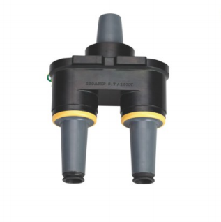
A Double-Pass Casing Connector adds a second compatible connection path at an equipment interface. A Loadbreak Junction creates a separate connection point within the cable network. Although both products can be used in a 15kV 200A separable connector system, they solve different layout and operating problems.
YIEOU supplies the JY STT-15/200 15kV 200A Double-Pass Casing Connector for equipment-side dual-path arrangements and the JY MP-15kV 200A Loadbreak Junction for cable branching, looping, splicing, and sectionalizing.
The correct choice does not begin with the product shape or the shared 200A rating. It begins with one question:
Should the additional connection be created at the equipment interface or at a separate point in the cable network?
Decide Where the Extra Connection Must Sit
The installation position is the clearest difference between the two configurations.
A Double-Pass Casing Connector expands one equipment-side connection position into two compatible paths. It is normally considered when a transformer, switchgear unit, ring main unit, or compact substation needs an incoming and outgoing cable arrangement around the same equipment interface.
A Loadbreak Junction places several compatible interfaces at a separate network position. It is more suitable when cables must meet at an independent branch, loop, splice, or sectionalizing point.
| Selection Point | Double-Pass Casing Connector | Loadbreak Junction |
| Main purpose | Adds a second path at one equipment interface | Creates an independent cable connection point |
| Typical layout | One incoming and one outgoing cable | Loop, tap, splice, branch, or sectionalizing point |
| Installation position | Equipment bushing or casing position | Cabinet, vault, bracket, or separate mounting area |
| Number of paths | Best for one clearly defined additional path | Better for several coordinated cable paths |
| Main space concern | Two cables concentrated near the equipment | Separate mounting and cable-routing space |
| Maintenance position | Work remains at the equipment compartment | Network access can be separated from the equipment |
| Expansion method | Expands the equipment interface | Expands the cable network |
Neither product is automatically better.
A double-pass arrangement may be simpler in one transformer compartment, while a junction may provide a clearer system structure where several feeders must be coordinated. The system diagram and installation space should decide the configuration.
Read the Single-Line Diagram Before Choosing
Do not select the product from its appearance alone.
Two components may both carry a 15kV 200A rating while occupying completely different positions in the system. The single-line diagram should first show where the existing cable terminates and where the additional path must begin.
The project should identify whether the circuit is:
- A radial feeder ending at one transformer
- A loop entering and leaving the same transformer
- A feeder with one or more branch circuits
- A sectionalized underground distribution line
- A compact connection with surge protection
- A network prepared for a confirmed future extension
The equipment drawing should then be checked against the single-line diagram. It needs to show the available bushing or casing positions, phase spacing, cable entry direction, compartment depth, mounting structure, and operating clearance.
An electrically reasonable configuration may still be difficult to install when the cabinet cannot accommodate the elbow connectors, cable bends, grounding leads, and operating tools.
Use Double-Pass When One Extra Path Is Enough
A Double-Pass Casing Connector is suitable when one equipment position needs two compatible 200A connection paths.
A common example is a pad-mounted transformer with one incoming feeder and one outgoing feeder continuing to the next transformer. Both cable paths belong to the same transformer position. In this layout, adding a second path at the equipment interface may be more direct than installing a separate junction nearby.
The second interface may also support a compatible surge arrester or another clearly specified accessory, depending on the approved system design.
The important point is that the additional path has a defined purpose.
A double-pass configuration should not be selected simply because an unused interface might be helpful in the future. The project should confirm whether the second position will connect:
- An outgoing feeder
- A second cable in a loop
- A compatible elbow surge arrester
- A protected spare for a confirmed expansion plan
- Another approved 200A system accessory
When only one additional path is required, the double-pass structure can keep the system compact and avoid creating another independent connection location.
Two Cables Still Need Enough Cabinet Space
A compact product does not guarantee a compact installation.
A Double-Pass Casing Connector places two interfaces around one equipment position. This means two elbows, two cables, grounding leads, and related accessories may need to occupy the same compartment area.
The design should confirm:
- Cable entry direction
- Minimum cable bending radius
- Elbow orientation
- Phase-to-phase spacing
- Grounding lead routing
- Operating-stick access
- Clearance from the cabinet door
- Space for removing one elbow
- Distance from barriers and internal structures
A frequent layout problem occurs when a compartment designed for one cable is expected to hold two cables without changing the internal arrangement.
The cables may technically reach the interfaces, but one or both may remain under mechanical stress. The cable bend may push against the elbow, twist the connector body, obstruct an adjacent phase, or make maintenance difficult.
The connector should not be used to pull the cable into position. Cable supports and entry points should carry the cable weight and control the bending force.
Use a Junction for Independent Branching
A Loadbreak Junction is more appropriate when the required connection belongs to the cable network rather than to one equipment interface.
The junction brings several compatible cable paths together at an independent position. It may be installed inside a cable branch box, pad-mounted enclosure, underground vault, sectionalizing cabinet, or another suitable mounting location.
Typical applications include:
- Establishing an underground cable loop
- Creating a feeder tap
- Joining several cable directions
- Providing a cable splice point
- Separating one feeder into multiple branches
- Creating a sectionalizing location
- Supporting equipment replacement arrangements
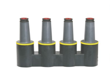
The YIEOU JY MP-15kV 200A Loadbreak Junction is intended for these multi-point connection requirements within a compatible 15kV 200A separable connector system.
Keep Complex Branching Away from the Equipment
A junction is especially useful when the cable branching function should not depend on one transformer or switchgear position.
Consider an underground feeder supplying several pad-mounted transformers. If every branch is concentrated at one transformer compartment, the cable routing can become crowded and future changes may depend on access to that specific transformer.
A separately mounted Loadbreak Junction gives the branch or loop its own defined position. This can make the network structure easier to identify and allow the equipment connection to remain relatively simple.
A junction is usually the stronger option when:
- Three or more cable paths must be coordinated
- The branch point is physically separated from the equipment
- Several future feeder directions have already been confirmed
- The equipment compartment cannot hold additional cables
- Independent network access is required
- The operating plan needs a clear sectionalizing position
- Cable testing or grounding should occur away from the equipment
This does not mean every underground system requires a junction. When the system only needs one incoming and one outgoing cable at a transformer, a compatible double-pass configuration may remain simpler.
Do Not Choose by Port Count Alone
The number of visible interfaces does not explain the complete system function.
A two-way junction and a double-pass component may appear to provide a similar number of connection positions. However, one expands the cable network while the other expands an equipment interface.
The more useful questions are:
- Where should the cable paths meet?
- Is the connection part of the equipment or the network?
- How many cables must be connected now?
- Will the position be used for operation or sectionalizing?
- Can the cables enter without excessive bending?
- Does the equipment provide enough working space?
These questions prevent a common mistake: selecting a product because it appears to provide the correct number of ports without checking where those ports belong in the system.
One Incoming and One Outgoing Cable Favor Double-Pass
A transformer loop is one of the clearest applications for a Double-Pass Casing Connector.
Suppose one underground cable enters a pad-mounted transformer and another cable leaves the transformer to supply the next point in the loop. Both cables are directly associated with the same equipment position.
When the transformer has a compatible casing structure and sufficient compartment space, a double-pass configuration can provide the two required paths without adding a separate junction enclosure.
This arrangement can reduce the number of independent connection positions, but it still requires careful cable routing. The incoming and outgoing cables must approach the interfaces without crossing, twisting, or applying excessive force to the connector system.
Several Cable Routes Usually Need a Junction
A feeder tap becomes more complicated when the main circuit continues in more than one direction.
For example, an underground feeder may need to continue forward while also supplying a side branch. Another cable may be reserved for a second transformer or a future section that has already been included in the project plan.
This is no longer a simple two-path equipment connection.
A Loadbreak Junction provides a clearer arrangement because the cable routes can be organized around a dedicated network connection point. The junction can also make the feeder functions easier to identify during testing, maintenance, and fault isolation.
When several cable routes are involved, trying to concentrate every connection around one equipment bushing can create unnecessary congestion.
Every Spare Interface Must Be Protected
A spare interface is not maintenance-free.
If a double-pass connector or junction includes an unused energized position, the interface must be protected with a compatible rated insulating cap or another approved accessory. A shipping cover is only intended to protect the surface during transportation and storage. It is not a substitute for an electrical insulation accessory.
The project should define:
- Why the spare interface is required
- Whether it will remain energized
- Which insulating cap will be installed
- How the shield and grounding arrangement will be completed
- Whether the spare position will remain accessible
- How it will be identified in the system documents
Adding ports without a clear expansion plan can increase the number of accessories, installation steps, and possible contamination points.
Future flexibility should be based on a defined electrical plan, not only on the possibility that another cable may be added someday.
Cabinet Space Can Change the Final Choice
The preferred electrical configuration may not fit the physical installation.
A double-pass arrangement appears compact because it remains close to the equipment. However, the two connected cables may require more usable compartment depth than expected.
A junction requires a separate mounting position, but it can sometimes improve cable routing by allowing cables to enter from more practical directions.
Before confirming the product, review the dimensional drawing and check:
- Distance from the interface to the cabinet door
- Depth required behind each elbow
- Separation between adjacent phases
- Distance from the cable entry to the interface
- Position of cable cleats and supports
- Space for installation and operating tools
- Clearance for voltage testing and grounding
- Space for removing one connector without disturbing another
A few dimensional differences can determine whether an apparently compact design is actually practical.
YIEOU can review the product arrangement more accurately when customers provide the cabinet drawing, equipment interface drawing, and cable entry dimensions together with the electrical diagram.
Make Future Isolation and Testing Easier
The connection layout should support maintenance as well as initial installation.
A medium-voltage cable system may later require inspection, voltage testing, grounding, cable replacement, surge arrester replacement, or network extension.
A double-pass arrangement keeps this work at the transformer or switchgear compartment. This can be practical when the compartment has clear access and the operating team already expects to work at that location.
A Loadbreak Junction creates a separate network position. This may improve access when the equipment compartment is crowded or when the cable system requires its own sectionalizing point.
Before finalizing the layout, the project should answer:
- Which cable may need to be isolated?
- Which interfaces may remain energized?
- Where will voltage testing take place?
- Where will grounding accessories be installed?
- Can one cable be removed without disturbing the others?
- Can operators identify every feeder direction?
- Does the layout match the site switching procedure?
A configuration that is easy to assemble but difficult to isolate may create avoidable problems during future maintenance.
Loadbreak Operation Requires a Matched System
The word “loadbreak” does not mean every component can be disconnected under any operating condition.
Loadbreak capability depends on the complete matched system, including:
- Loadbreak elbow connector
- Operating probe
- Junction or equipment interface
- Cable and conductor
- Voltage and current ratings
- Installation condition
- Approved operating tool
- Switching procedure
A Loadbreak Junction provides compatible interfaces within a loadbreak connector system. It does not replace a circuit breaker, protective relay, or dedicated switchgear device.
The same caution applies to a Double-Pass Casing Connector. Its use in a 200A separable connector arrangement does not automatically confirm that every attached accessory can be operated under load.
The project must confirm whether the installed elbow is a loadbreak or deadbreak design and whether the complete assembly has the required operating rating.
Only trained personnel should perform loadbreak operations under approved system and safety procedures.
Confirm Compatibility Before Comparing Layouts
The layout decision matters only after electrical and mechanical compatibility have been confirmed.
A Double-Pass Casing Connector and Loadbreak Junction cannot be selected only from the nominal voltage and current printed in the product name.
The complete system must match in several areas.
Use the Correct Voltage Class
The project should provide:
- Nominal system voltage
- Maximum operating voltage
- Equipment insulation class
- Required impulse withstand level
- Cable voltage class
- Applicable project standard
A 15kV component should be coordinated with the complete 15kV connection system. It should not be mixed with another interface only because both products have a 200A rating.
Keep Every Interface in the Same Family
The elbow connector, probe, bushing insert, casing seat, Double-Pass Casing Connector, Loadbreak Junction, insulating cap, grounding elbow, and surge arrester must use compatible interfaces.
Similar appearance does not prove that two parts can be connected safely.
Equipment drawings and product drawings should be checked before production and installation.
Match the Connector to the Actual Cable
Cable data affects the elbow connector and the complete accessory set.
YIEOU normally needs:
- Conductor material
- Conductor cross-sectional area
- Strand construction
- Diameter over conductor
- Diameter over insulation
- Insulation material
- Metallic screen structure
- Overall cable diameter
Nominal conductor size alone is not enough.
Two cables with the same conductor area may have different insulation diameters, strand structures, and screen arrangements. These differences can change the required connector body, contact, and installation accessories.
Rate the Complete Current Path
Every current-carrying component must support the intended circuit.
The conductor, contact, elbow, probe, junction interface, bushing component, and casing connector should form a compatible 200A current path.
A higher rating on one individual product cannot compensate for an incompatible or undersized component elsewhere in the system.
Send YIEOU the Complete Connection Plan
Ordering by product name alone can produce a component that matches the catalogue description but not the actual equipment.
For a Loadbreak Junction or Double-Pass Casing Connector project, provide the following information.
Send the Single-Line Diagram
Show the incoming feeder, outgoing feeder, branch circuits, transformer positions, normal open point, and any planned spare circuits.
Send the Equipment Interface Drawing
Identify the bushing well or casing seat, mounting structure, interface dimensions, phase spacing, and compartment depth.
Send the Complete Voltage Data
Provide nominal voltage, maximum system voltage, insulation class, and required electrical test level.
Send the Actual Cable Specification
Include conductor material, conductor size, cable construction, insulation diameter, screen structure, and overall diameter.
Explain the Second Connection Path
State whether the added interface is intended for:
- An outgoing feeder
- A cable loop
- A feeder branch
- A surge arrester
- A sectionalizing point
- A grounding or testing accessory
- A confirmed future circuit
Show the Available Installation Space
Provide the cabinet depth, cable entry position, mounting area, door clearance, and any cable bending limitations.
List the Required Accessories
Identify the required elbows, probes, casing components, insulating caps, grounding accessories, surge arresters, brackets, and installation kits.
YIEOU combines medium-voltage cable accessory manufacturing with product configuration, technical drawing review, testing, quality control, and OEM or ODM support.
This allows the Loadbreak Junction or Double-Pass Casing Connector to be considered together with the matching elbow connectors, cable data, insulating accessories, grounding products, and equipment interfaces rather than treated as an isolated part.
For repeat orders, confirming the complete configuration at the beginning also helps maintain consistent interfaces, accessory combinations, documentation, and packaging between production batches.
Follow Five Steps Before Ordering
The selection can be simplified into five steps.
Locate the New Connection
Confirm whether the additional path must be created at the equipment interface or at an independent point in the cable network.
Count the Required Cable Paths
Count the cables and accessories that will actually be installed. Do not treat an undefined future possibility as a confirmed path.
Define the Operating Function
Identify whether the position will be used for loop feed, tapping, sectionalizing, surge protection, testing, grounding, or equipment replacement.
Check the Available Space
Verify cabinet depth, cable entry direction, bending radius, phase spacing, mounting area, and maintenance access.
Match the Complete Accessory Set
Confirm the voltage class, interface type, cable specification, elbow connector, insulating cap, grounding accessory, and operating procedure.
When one equipment position needs one clearly defined additional 200A path, the JY STT-15/200 Double-Pass Casing Connector may provide the more direct arrangement.
When the system needs an independent loop, tap, splice, branch, or sectionalizing point, the JY MP-15kV 200A Loadbreak Junction is normally the more suitable direction.
FAQ
Can a Double-Pass Casing Connector replace a Loadbreak Junction?
Not in every system. A double-pass connector expands one equipment position, while a junction creates an independent cable network connection point.
Is a Loadbreak Junction always better for expansion?
No. It is useful when several defined cable paths or a separate branch point are required. An unnecessary junction adds space, accessories, and installation work.
Can both products appear in the same 200A system?
Yes. They can serve different positions in the same system when their voltage ratings, interfaces, and connected accessories are compatible.
Does a 15kV 200A rating guarantee compatibility?
No. The interface design, insulation structure, equipment drawing, cable specification, and accessory family must also match.
Can a shipping cover protect an unused energized port?
No. An energized unused interface requires a compatible rated insulating cap or another approved protective accessory.
Can every loadbreak connector be disconnected under load?
No. Loadbreak operation is only permitted within the rating of the complete matched system and under an approved procedure.
Conclusion
Choose the configuration by locating the additional connection.
A Double-Pass Casing Connector is suitable when a transformer, switchgear unit, or other equipment position needs two compatible 200A paths. It can support a compact incoming-and-outgoing arrangement without creating a separate network junction.
A Loadbreak Junction is more suitable when the project needs an independent cable branching, looping, splicing, or sectionalizing point. It provides a clearer position for coordinating several cable routes and separating the network connection function from one specific piece of equipment.
The shared 15kV 200A rating does not make the two products interchangeable.
The final choice should coordinate the single-line diagram, equipment interface, cable specification, available space, operating procedure, maintenance access, and complete accessory set.
By reviewing these details before production, YIEOU can match the JY STT-15/200 Double-Pass Casing Connector or JY MP-15kV 200A Loadbreak Junction with the appropriate elbows, casing components, insulating caps, grounding accessories, and surge protection products for a complete 200A separable connector system.