
In a medium-voltage cable system, Separable Connectors and Cable Joints both provide electrical connection and insulation continuity, but they are designed for very different positions in the network.
A Separable Connector is mainly used where a medium-voltage cable connects to equipment such as switchgear, a ring main unit, or a transformer. A Cable Joint, also commonly called a cable splice, is mainly used where one cable section needs to connect to another.
The easiest way to understand the difference is:
- A Separable Connector connects a cable to equipment.
- A Cable Joint connects one cable section to another.
That difference affects almost everything else, including product structure, installation position, interface requirements, maintenance, and how the accessory should be selected.
For utilities, switchgear manufacturers, electrical contractors, distributors, and other companies working with medium-voltage distribution systems, choosing between the two starts with one simple question:
What exactly needs to be connected?
What Is a Separable Connector?
A Separable Connector is a medium-voltage cable accessory used to connect an insulated power cable to a compatible equipment bushing or interface.
Typical applications include:
- Ring main units
- Medium-voltage switchgear
- Pad-mounted transformers
- Distribution transformers
- Cable distribution cabinets
- Compact substations
- Other medium-voltage equipment using compatible bushing interfaces
Instead of permanently joining two cable lengths, the Separable Connector forms the connection between the prepared cable end and the equipment.
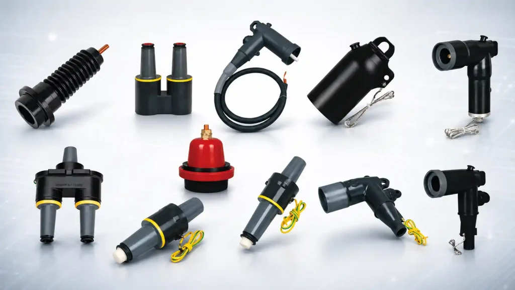
Common forms include:
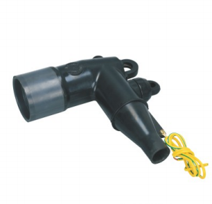
- Elbow connectors
- T-body connectors
- Straight connectors
- Loadbreak connectors
- Deadbreak connectors
In screened designs, the connector body also helps control the electrical field around the cable termination area, while the conductive outer screen can be connected to earth as part of the overall system design.
One of the main characteristics of this type of accessory is that the connector can be separated from the equipment interface when the operating conditions and safety procedures allow.
However, the word “separable” does not mean that every connector can be disconnected while the circuit is energized.
A loadbreak connector is specifically designed for loadbreak operation within its applicable ratings and operating procedures. A deadbreak connector, by comparison, is normally connected or disconnected only after the circuit has been de-energized.
That distinction should always be considered when selecting a Separable Connector for a medium-voltage system.
What Is a Cable Joint?
A Cable Joint connects two sections of power cable so they can operate as part of one continuous electrical circuit.
Cable joints are commonly used when:
- A cable route is longer than one available cable drum
- Two cable sections need to be connected during installation
- A damaged section of cable needs to be replaced
- An existing cable circuit is being extended
- Different compatible cable sections need to be connected
- An underground cable route requires an intermediate connection
The purpose of the joint is not simply to connect the two conductors.
A properly matched medium-voltage Cable Joint also needs to restore the important electrical and protective functions of the cable across the joint location.
Depending on the cable construction and joint design, this may include:
- Conductor continuity
- Electrical insulation
- Electrical field control
- Metallic screen continuity
- Earthing continuity
- Moisture sealing
- Outer environmental protection
- Mechanical protection
Cable jointing systems may use cold-shrink, heat-shrink, premolded, or other engineered insulation technologies depending on the cable and application.
Once installed, a conventional inline Cable Joint normally remains as part of the cable route. It is not usually treated as an equipment connection point that will be routinely separated during normal maintenance.
Specialized disconnectable joint systems do exist, but they serve more specific applications and should not be confused with a conventional equipment Separable Connector.
Separable Connector vs Cable Joint: Key Differences
Although both belong to the broader medium-voltage cable accessory category, their functions are quite different.
| Comparison | Separable Connector | Cable Joint |
| Main function | Connects a cable to electrical equipment | Connects one cable section to another |
| Typical location | Switchgear, transformer, RMU or other equipment interface | Along the cable route |
| Connection type | Cable-to-equipment | Cable-to-cable |
| Interface requirement | Must match the equipment bushing/interface | Must match the cables being joined |
| Typical structure | Elbow, T-body, straight, loadbreak or deadbreak | Inline jointing system |
| Separation | Can be disconnected under the conditions specified for the connector type | Normally remains installed after jointing |
| Main project purpose | Equipment connection and network access | Cable extension, repair or route continuity |
| Selection focus | Cable data plus equipment interface | Cable construction on both sides |
This is why the two products are generally not interchangeable.
If a medium-voltage cable needs to connect to a transformer bushing, a Separable Connector is normally the relevant accessory.
If two underground cable lengths need to be joined halfway along a route, a Cable Joint is normally the more appropriate solution.
The Main Difference Is Where the Connection Happens
When comparing a Separable Connector with a Cable Joint, it is easy to focus on their construction.
For practical project selection, however, the installation position is usually more important.
When the cable connects to electrical equipment
If the cable connects to an RMU, switchgear panel, transformer, or another medium-voltage device through a defined bushing interface, a Separable Connector is generally required.
The connector must match both sides of the connection:
the cable and the equipment interface.
That means selection may involve:
- System voltage
- Current rating
- Bushing interface
- Cable conductor size
- Cable insulation diameter
- Insulation material
- Cable screen construction
- Copper or aluminum conductor
- Required connector configuration
Two projects can use cables of the same voltage class while still requiring different Separable Connectors.
For example, their conductor cross-sections may differ, their insulation diameters may fall within different ranges, or the connected equipment may use different bushing interfaces.
This is why voltage alone is not enough to determine the correct connector.
When one cable connects to another cable
If the requirement is to continue a cable route by connecting two cable sections together, the project normally requires a Cable Joint.
In this case, there is no switchgear or transformer bushing to match.
Instead, the important question becomes whether the joint is suitable for the cable constructions on both sides.
The joint needs to maintain the required conductor, insulation, screen, and sealing performance through the connection area.
This distinction makes the basic choice much easier:
Equipment connection → Separable Connector
Cable extension or repair → Cable Joint
Separable Connectors Provide More Flexibility at Equipment Interfaces
Separable Connectors are widely used around medium-voltage equipment because they provide a defined connection between the cable system and the equipment bushing.
That becomes useful when equipment may eventually need to be inspected, replaced, upgraded, or reconfigured.
After the circuit has been placed in the correct operating condition and the applicable safety procedures have been followed, the cable connection can be separated from the equipment rather than being permanently built into it.
This makes Separable Connectors particularly suitable for several common medium-voltage applications.
Ring Main Units
RMUs often have limited internal installation space and require compact cable connections.
Screened elbow or T-body connectors are commonly used to connect incoming and outgoing medium-voltage cables to the equipment bushings.
The specific connector depends on the interface, cable dimensions, current requirement, and network design.
Transformers
Medium-voltage cables may connect to transformer bushings through Separable Connectors rather than conventional exposed cable terminations.
This arrangement is common in underground and compact distribution systems where a plug-in or screened equipment interface is preferred.
Loadbreak or deadbreak configurations may be selected depending on the equipment design and operating requirements.
Medium-Voltage Switchgear
Separable Connectors are also widely used where polymeric insulated cables connect to compatible medium-voltage switchgear.
A properly matched screened connector provides a compact cable interface while maintaining the required insulation and field-control functions around the connection.
Systems That May Be Reconfigured
Medium-voltage equipment is not always expected to remain unchanged throughout the entire service life of a network.
Switchgear may be replaced, transformers may be upgraded, and network arrangements may change.
A separable equipment interface can make these changes more practical than a connection arrangement intended to remain permanently installed.
This does not mean Separable Connectors should be treated as ordinary plugs that are disconnected frequently.
The connector type, equipment design, circuit condition, operating tool, and applicable procedures still determine when and how the connection can be separated.
Cable Joints Are Designed to Maintain Cable Route Continuity
Cable Joints solve a different problem.
Their purpose is usually to make two cable sections function as one continuous route.
Consider a medium-voltage underground feeder running between a substation and a remote distribution point.
If the route is longer than the cable length available on a single drum, several cable sections may be required.
A Cable Joint can connect those sections along the route.
A similar situation occurs when a damaged part of an existing cable has to be removed.
Instead of replacing the entire feeder, the damaged section may be cut out and replaced. Cable Joints can then connect the replacement section to the existing cable on both sides.
In these applications, the joint is expected to remain part of the cable system after installation.
The priorities therefore include:
- Reliable conductor connection
- Stable electrical field control
- Insulation continuity
- Metallic screen continuity
- Moisture protection
- Mechanical protection
- Compatibility with the cable construction
- Consistent installation quality
Rather than providing access to electrical equipment, the Cable Joint effectively becomes part of the cable route itself.
Separable Connectors and Cable Joints Are Often Used in the Same Network
A project does not necessarily choose either Separable Connectors or Cable Joints.
Many medium-voltage networks use both because they perform different jobs.
For example, consider a cable running from medium-voltage switchgear to a transformer.
At the switchgear end, a Separable Connector may connect the cable to the switchgear bushing.
If the cable route is too long for a single cable drum, a Cable Joint may be installed somewhere along the route.
At the transformer end, another Separable Connector may connect the cable to the transformer.
The circuit could therefore look like this:
Switchgear → Separable Connector → MV Cable → Cable Joint → MV Cable → Separable Connector → Transformer
This example also explains why cable accessories should not be selected only by voltage class.
Even within the same 12kV, 15kV, 24kV, or 35kV network, different locations may require completely different accessories.
One connection may depend heavily on the equipment bushing interface, while another depends almost entirely on cable construction and jointing requirements.
When Should You Use a Separable Connector?
A Separable Connector is generally the better choice when:
- A medium-voltage cable needs to connect to switchgear
- The cable connects to an RMU
- The cable connects to a transformer bushing
- The equipment uses a compatible separable interface
- A screened equipment connection is required
- The application requires a loadbreak or deadbreak connector
- Equipment may need to be replaced or accessed later
In these situations, the connector becomes the interface between the cable and the equipment.
The next step is therefore to make sure the connector fits both.
When Should You Use a Cable Joint?
A Cable Joint is generally more appropriate when:
- Two cable lengths need to be connected inline
- A long cable route requires several cable sections
- A damaged cable section needs replacement
- An existing cable route is being extended
- Cable-to-cable continuity is the main requirement
Here, the focus is not on the equipment interface but on the two cables being joined.
Their voltage class, conductor, insulation dimensions, screen construction, and other cable characteristics all influence joint selection.
There are also more specialized network arrangements.
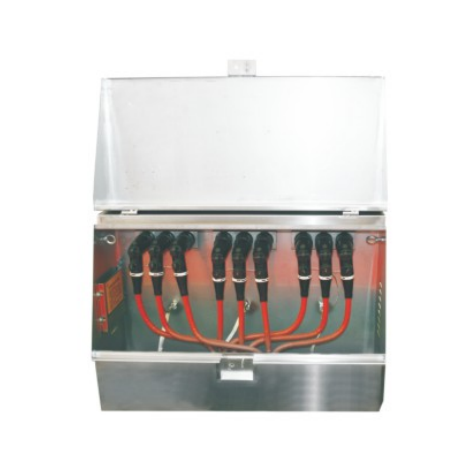
Cable branching systems, junction boxes, and disconnectable jointing systems can make the boundary between the two product categories less obvious.
When the application is unusual, looking at the actual network diagram is usually more useful than trying to choose an accessory from its name alone.
What Should Be Checked When Selecting a Separable Connector?
For a Separable Connector, the voltage class is only the starting point.
A connector that matches the system voltage may still be unsuitable if the cable dimensions or equipment interface are different.
The main information worth checking includes:
System Voltage
The connector must be suitable for the applicable medium-voltage system.
Voltage class is one of the first filters during product selection, but it should not be used by itself.
Current Rating
The required current rating affects the connector family and application.
For example, different network configurations may use different current classes and corresponding bushing interfaces.
Cable Conductor Size
The conductor cross-section influences the conductor connection and accessory configuration.
The conductor material should also be confirmed, particularly where copper and aluminum conductors require different connection arrangements.
Cable Insulation Diameter
This is one of the most important dimensions when matching a premolded Separable Connector to a cable.
Two cables with the same conductor size do not necessarily have the same insulation diameter.
The actual cable datasheet is therefore more reliable than selecting only from nominal conductor size.
Cable Construction
The insulation material, metallic screen, semiconductive layers, and overall cable structure should be considered when selecting the complete accessory configuration.
Equipment Bushing Interface
This is one of the biggest differences between Separable Connector and Cable Joint selection.
The connector must physically and electrically match the bushing interface used by the switchgear, transformer, or other equipment.
Without confirming the interface, choosing only according to voltage and cable size can lead to a mismatch.
Selecting the Right Accessory Starts with the Connection Point
For most projects, the difference between a Separable Connector and a Cable Joint is not difficult once the actual application is clear.
If the question is:
“How do we connect this medium-voltage cable to the switchgear or transformer?”
the project is usually looking for a Separable Connector or another suitable cable termination solution.
If the question is:
“How do we connect these two cable lengths together?”
the project is usually looking for a Cable Joint.
From there, the detailed electrical and dimensional parameters can be checked.
This approach is much more reliable than starting with a product catalogue and trying to decide between accessories only from their appearance.
YIEOU Separable Connectors for Medium-Voltage Cable Systems
At YIEOU, we manufacture and supply Separable Connectors and related medium-voltage cable accessories for switchgear, transformers, ring main units, cable distribution equipment, and other power distribution applications.
For us, supplying the right Separable Connector is not simply a matter of matching the voltage printed on the cable.
The connector needs to work with the actual cable dimensions, conductor specification, current requirement, and equipment bushing interface used in the project.
That is why a cable datasheet, equipment bushing information, or a simple connection drawing is often useful when comparing different connector options. These details help us narrow down the suitable configuration more accurately, especially when customers are dealing with several cable specifications or equipment types in the same project.
As a Separable Connector manufacturer and supplier, YIEOU works with utilities, electrical distributors, switchgear manufacturers, contractors, and project companies requiring medium-voltage cable connection solutions.
Whether the application uses an elbow connector, T-body connector, loadbreak connection, deadbreak connection, or another compatible configuration, our focus is to make sure the cable accessory matches the actual connection point rather than selecting from voltage class alone.
FAQ
Is a Separable Connector the same as a Cable Joint?
No. A Separable Connector normally connects a medium-voltage cable to equipment such as switchgear, an RMU, or a transformer through a compatible bushing interface. A Cable Joint normally connects two cable sections together.
Can a Separable Connector be used to join two cables?
A conventional equipment Separable Connector is not normally used as a direct replacement for an inline Cable Joint. However, specially designed junction systems can use Separable Connectors for cable branching or network connection applications.
Can a Cable Joint be disconnected?
A conventional inline Cable Joint is normally intended to remain installed as part of the cable route rather than being routinely disconnected. Specialized disconnectable joint systems are available for certain applications.
Can every Separable Connector be disconnected under load?
No. Only connectors specifically designed and rated for loadbreak operation should be operated under the applicable load conditions and approved procedures. Deadbreak connectors normally require the circuit to be de-energized before connection or disconnection.
What information is useful when selecting a Separable Connector?
System voltage, current rating, cable conductor size, conductor material, insulation diameter, cable construction, equipment type, and bushing interface are all useful. A cable datasheet or equipment drawing can also help us match the Separable Connector more accurately.