
Quick Answer
Separable connectors are commonly used in utility-scale solar farms where medium-voltage collector cables connect to step-up transformers, ring main units, switchgear, cable branch equipment, and other compatible medium-voltage interfaces.
The connector should not be selected according to the total MW rating of the solar project. What matters is the condition at the individual connection point: the equipment bushing interface, system voltage, circuit current, cable construction, actual insulation diameter, operating requirement, and available installation space.
For projects with many repeated inverter-transformer stations, these parameters should be confirmed before the full accessory quantity is released. A mismatch that appears small during purchasing can become a serious site problem when the same configuration is repeated across dozens of stations.
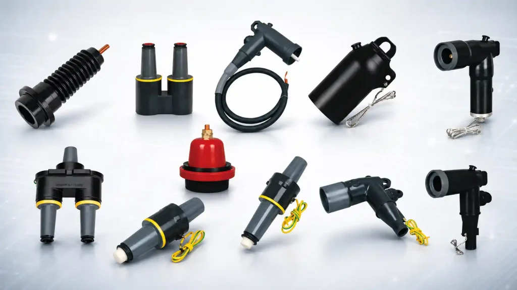
YIEOU manufactures medium-voltage Separable Connector systems and related cable accessories for transformers, RMUs, switchgear, branch connections, and underground distribution systems. For solar projects, the most reliable approach is to treat the cable, connector, contact, and equipment bushing as one complete interface rather than selecting each component independently.
Where Are Separable Connectors Used in a Solar Farm?
A solar farm contains DC circuits, inverter outputs, low-voltage AC sections, and medium-voltage distribution equipment. Separable connectors are mainly used after the inverter output has been stepped up to the MV collector level.
A simplified power path may be represented as:
PV arrays → inverter → step-up transformer → MV collector cable → RMU or switchgear → collector feeder → project substation
The exact arrangement depends on the project. Some plants use centralized inverter stations, while others use distributed transformer stations or compact substations. Even when the overall electrical architecture is similar, the cable connection details can vary considerably.
This is why it is more useful to ask where the cable is terminating than simply to ask which connector is used in a solar farm.
Connections at the Step-Up Transformer
The medium-voltage side of the inverter step-up transformer is one of the most common locations for a separable connector.
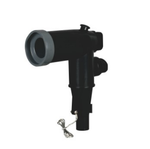
Depending on the transformer design, the equipment may use a compatible bushing interface for an elbow connector, T-body connector, or another separable connection system.
The transformer drawing is therefore an important starting point.
Before selecting the separable connector, the project team should verify which bushing interface is installed and how the cable will enter the transformer compartment. Once the equipment side is known, the cable specification can be matched to the appropriate connector body and contact.
This sequence is important because choosing the connector first and checking the transformer interface later can easily result in a mismatch.
Connections at RMUs
Ring main units are frequently used in solar collector networks to connect transformer stations and feeder sections into an organized medium-voltage distribution system.
An RMU may have several cable positions serving different purposes. One may receive power from a transformer station, another may continue the collector feeder, and another may be reserved for future expansion.
Although these positions may appear similar, they do not always require identical cable accessories.
A transformer feeder may operate at a different current from a main collector circuit, and a spare interface may require a compatible insulation cap rather than a cable connector. The cable size and entry direction may also differ from one position to another.
The RMU should therefore be reviewed as a group of individual interfaces rather than assuming that every bushing position uses the same connector arrangement.
Connections at Medium-Voltage Switchgear
As collector circuits converge toward the project substation, the current carried by individual feeders may increase.
Connections at medium-voltage switchgear may therefore use different connector systems from those used at smaller distributed transformer stations.
Higher-current deadbreak systems are common in many such applications, but the final selection must still follow the actual switchgear interface and cable design.
The key point is that current rating alone does not define the connector.
A 600A or 630A rating may describe the continuous current capability, but it does not automatically identify the physical interface or guarantee compatibility with a particular switchgear bushing.
Why Connector Coordination Matters More in Solar Farms
Solar farms create a particular engineering and procurement challenge because the same station design is often repeated many times.
If one incorrect connector is ordered for a single industrial installation, the problem may be limited to one location.
If the same incorrect connector specification is repeated across 50 or 100 inverter-transformer stations, the consequences are very different. Installation can stop across multiple work areas, replacement parts may need to be reordered, and commissioning schedules may be affected.
For this reason, standardization is valuable only after the first connection has been verified correctly.
A solar project may use the same transformer, RMU, and cable design across many power blocks. Once the equipment interface, cable dimensions, conductor arrangement, current duty, and installation space have all been checked, the project can establish a standard accessory set for that particular station type.
This is a much safer approach than choosing a generic “15kV connector” or “630A connector” and applying it throughout the project.
Start With the System Voltage, but Do Not Stop There
Voltage class is the first basic selection boundary.
Solar collector systems may operate at 10kV, 15kV-class, 20kV, 22kV, 24kV-class, 33kV, 35kV, or another project-specific medium-voltage level.
The connector and mating equipment must therefore have an insulation rating suitable for the system.
However, voltage only determines part of the requirement.
Two connector systems may both be suitable for a 15kV-class network while using different bushing interfaces, current ratings, cable ranges, contacts, or operating methods.
This is why a request such as “we need a 15kV separable connector” is still incomplete.
For ANSI/IEEE-style shielded separable insulated connector systems, IEEE 386 covers loadbreak and deadbreak systems used on medium-voltage distribution networks. Where this type of interface is specified, the project should confirm both the electrical rating and the applicable interface system rather than relying on nominal voltage alone.
200A, 600A, or 630A: Select for the Circuit, Not the Solar Farm Capacity
It is common to see solar project inquiries where connector current rating is associated directly with the total plant capacity.
For example, a 100MW solar farm may be assumed to require 600A connectors because the project itself is large.
That is not how the selection should be made.
A connector carries the current of the individual circuit in which it is installed. A connector serving one distributed inverter-transformer station may carry a much lower current than a connector used on a major feeder closer to the substation.
Where 200A-Class Systems May Be Used
A 200A-class separable connector may be suitable for some transformer laterals, branch circuits, or other circuits where both the current duty and equipment interface match that system.
The final decision should be based on the actual transformer rating, circuit current, cable, and equipment bushing rather than the total output of the solar farm.
Where Higher-Current Systems Are Used
Collector feeders that carry power from several transformer stations may require a higher-current connection system.
Depending on the equipment platform and regional standard, this may involve 600A-class or 630A-rated connector systems.
These current ratings should not be treated as interface names.
Two products may both be described as 630A but still use different equipment-side interfaces. Their dimensions, mating components, and applicable standards therefore need to be checked before they are considered interchangeable.
This distinction is particularly important on international solar projects where transformers, RMUs, cables, and accessories may be sourced from different countries or manufacturers.
Confirm the Equipment Bushing Interface Before Selecting the Connector
One of the most useful documents during connector selection is the equipment interface drawing.
For a transformer or RMU connection, the drawing normally provides a much stronger basis for model matching than the equipment name alone.
The connector must physically and electrically mate with the bushing installed on the equipment. This means the interface design, current class, dimensions, and applicable standard all matter.
When the equipment interface is unclear, a clear bushing drawing or detailed photograph can often prevent incorrect assumptions.
The complete connection should always be considered as:
MV cable → cable contact → connector body → mating interface → equipment bushing
If any part of this chain is incompatible, the connection is not correctly selected.
This is also why the transformer supplier, RMU supplier, cable supplier, and accessory supplier should ideally work from the same interface information during the engineering stage.
Cable Conductor Size Alone Is Not Enough
Solar project cable schedules normally specify conductor sizes such as 70mm², 120mm², 185mm², 240mm², or 300mm².
This information is necessary because the cable contact or compression lug must match the conductor.
However, conductor cross-section does not determine the complete connector fit.
Why Actual Insulation Diameter Matters
The separable connector body interfaces with the prepared cable insulation, so the insulation diameter must fall within the connector’s intended range.
Two cables with the same nominal conductor size may still have different insulation diameters.
This can happen because of differences in cable standard, voltage class, insulation thickness, conductor construction, or manufacturer design.
For example, two 240mm² cables may appear equivalent in a simplified purchasing list, but one may require a different connector body range from the other.
This is why final selection should normally consider the actual cable construction rather than relying on conductor size alone.
A more useful cable specification includes the voltage class, conductor material, conductor size, insulation material, and actual insulation diameter.
These details allow the cable side of the interface to be matched much more accurately.
Copper and Aluminum Conductors Need the Correct Contact Arrangement
Solar collector systems may use either copper or aluminum conductors.
The separable connector body itself may be similar, but the current path also depends on the cable contact or lug installed on the conductor.
The contact therefore needs to be selected for the actual conductor material, size, and construction.
This becomes particularly important when aluminum cables are used on larger solar projects for cost and weight reasons.
The correct contact arrangement should be installed with the intended compression method and suitable tooling.
A correctly selected connector body cannot compensate for a conductor contact that does not match the cable.
For this reason, the conductor connection should be treated as part of the complete separable connector system rather than as a secondary accessory.
Loadbreak or Deadbreak?
Another important design question is whether the connector is intended to form part of a loadbreak or deadbreak system.
The answer depends on how the medium-voltage collector network is designed to operate.
Loadbreak Systems
A loadbreak connector is designed for specified switching operations when it is used with the correct mating interface and under the required operating conditions.
In some distribution networks, this provides additional operational flexibility.
However, the term “loadbreak” does not mean the connector can simply be disconnected whenever convenient.
The equipment, operating tool, circuit condition, and site procedure must all be suitable for the intended operation.
Deadbreak Systems
Deadbreak connectors are intended to be disconnected after the circuit has been de-energized and the required electrical safety procedures have been completed.
Higher-current collector connections frequently use this type of arrangement.
For solar farms, the selection should therefore follow the switching philosophy of the collector system.
If isolation and switching are performed through the RMU or switchgear, the cable connector may not need a switching function of its own.
Cable Routing and Installation Space Should Be Checked Early
A separable connector can be electrically correct and still be difficult to install.
This is particularly common in compact transformer stations and RMUs where the cable compartment is relatively small.
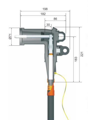
The cable may rise vertically from a trench, enter from the side, or approach the bushing from a restricted angle. These details influence how easily the connector can be installed and whether the cable can remain within its intended bending radius.
The installation layout should therefore be reviewed before the final accessory configuration is released.
What matters is not simply whether the connector can physically reach the bushing.
The installer needs enough room to prepare the cable correctly, position the connector, complete the connection, and support the cable without forcing it into an unsuitable bend.
Keep Mechanical Load Away From the Connector
Medium-voltage collector cables can be heavy, particularly at larger conductor sizes.
The separable connector should not become the mechanical support point for the cable.
If the weight of a vertical cable or the pulling force from an improperly routed cable is transferred directly to the connector, unnecessary stress can be applied to the prepared cable insulation, conductor contact, connector body, or equipment bushing.
Cable cleats, brackets, and other support arrangements should therefore carry the mechanical load before it reaches the interface.
This is especially important where cables rise from underground trenches into transformer or switchgear compartments.
Surge Protection Should Be Coordinated With the System Design
Solar farms often contain long medium-voltage cable runs, exposed equipment, transformers, switching devices, and a grid interconnection.
Overvoltage protection is therefore an important part of the overall electrical design.
However, this does not mean that every separable connector position requires a surge arrester.
Where the system design calls for surge protection at a compatible cable interface, a separable surge arrester configuration may be used.
The decision should follow the project’s insulation-coordination study and grounding arrangement.
The arrester rating, protective level, system voltage, and equipment insulation level should all be coordinated with the rest of the installation.
This is a system-level design decision rather than an accessory that should be added automatically to every solar transformer or RMU.
Spare Interfaces Should Be Planned Before Commissioning
Solar farms may be expanded or reconfigured during their operating life.
For this reason, RMUs and other medium-voltage equipment sometimes include spare cable positions for future feeders.
An unused interface should not simply remain exposed.
A compatible protective or insulating accessory may be required to maintain the intended insulation, sealing, shielding, and grounding conditions.
This should ideally be considered during the original accessory schedule rather than after the equipment is already installed.
If a project expects a future feeder to be added, the spare bushing interface should be identified and protected correctly from the beginning.
A Practical Selection Sequence for Solar Farm Projects
Selecting separable connectors for a solar farm is more reliable when the equipment side and cable side are reviewed together from the start.
In practice, the process should begin with the actual connection point rather than a catalogue model.
Start With the Equipment Connection
First determine where the medium-voltage cable will terminate.
This may be the MV side of a step-up transformer, an RMU, switchgear panel, cable branch unit, or another compatible medium-voltage device.
The equipment drawing should then be checked to confirm the bushing interface.
This step establishes which connector family can physically and electrically mate with the equipment.
Two RMUs may operate at the same voltage and current while still using different cable interfaces, so electrical ratings alone are not enough.
Match the Cable to the Connector Body and Contact
Once the equipment interface is known, the cable can be checked in more detail.
The conductor size determines part of the contact selection, but the conductor material, cable construction, and actual insulation diameter are equally important.
A 240mm² aluminum cable from one manufacturer may not have exactly the same insulation dimensions as another 240mm² cable.
The connector body must therefore match the cable insulation range, while the contact or lug must match the conductor.
This becomes especially important on projects where the cable, transformer, and accessories come from different suppliers.
Review Current Rating and Operating Requirement Together
After physical compatibility has been established, the electrical duty of the circuit should be reviewed.
The current rating should be selected for the actual transformer circuit or collector feeder where the connector is installed.
At the same time, the project should determine whether the interface is intended to be part of a loadbreak or deadbreak arrangement.
These two decisions are related to how the collector network is operated and maintained.
They should therefore be reviewed together with the equipment interface instead of being treated as separate catalogue selections.
Check Whether the Connection Can Be Installed Correctly
The final configuration should also be checked against the real cable compartment.
A suitable separable connector still needs enough room for cable preparation, positioning, bending, and support.
The cable should not be forced into a tighter bend simply to make the connector reach the bushing, and the weight of the cable should not be allowed to hang from the equipment interface.
For projects with many identical inverter-transformer stations, it is useful to verify one complete installation before releasing the full quantity of cable accessories.
Once the cable, connector, bushing, routing, and support arrangement have all been confirmed, the same configuration can then be repeated across identical stations with much greater confidence.
Common Connector Selection Problems in Solar Projects
Most separable connector problems do not begin during installation.
They begin earlier, when the purchasing or engineering specification does not contain enough information.
Selecting Only by Voltage
A description such as “15kV connector” is too broad for final selection.
The voltage rating may be correct while the bushing interface, current class, cable range, or operating type is still wrong.
Selecting Only by Conductor Size
A “240mm² connector” description also leaves important questions unanswered.
The insulation diameter, conductor material, cable construction, and equipment interface still need to be checked.
Treating Current Rating as the Interface
A 600A or 630A rating describes current capability, not universal physical compatibility.
The mating interface must still be verified.
Assuming Similar-Looking Parts Are Interchangeable
Bushings, inserts, connectors, junctions, caps, and surge arresters may appear similar even though they belong to different interface families.
Visual similarity is not enough to confirm compatibility.
Ignoring Installation Space Until the Equipment Arrives
Cable compartment dimensions should be considered during selection, not only during installation.
A separable connector may match the electrical interface while the cable still cannot be routed into position without excessive bending.
Releasing the Full Quantity Too Early
Large solar projects often require repeated accessory sets.
This makes early verification especially valuable.
Confirming one complete cable-to-equipment interface before releasing the full quantity can prevent the same mistake from being repeated across many stations.
How YIEOU Supports Solar Farm Medium-Voltage Connections
YIEOU manufactures medium-voltage cable accessories for transformer, RMU, switchgear, branch connection, underground distribution, and related power applications.
For solar farm projects, connector selection should be based on the complete interface rather than the connector body alone.
When we review a project, we look at how the cable, contact, connector, and equipment bushing work together, and we also consider whether the cable can be installed correctly within the available space.
This is particularly useful for large solar projects with repeated transformer stations.
Once one station configuration has been verified, the same accessory arrangement can be applied consistently to other stations using the same equipment and cable design.
The goal is not to use one connector type throughout the entire solar farm.
The goal is to establish the correct separable connector configuration for each repeated connection point.
FAQ
Are separable connectors used directly between solar panels and inverters?
Normally, no.
The separable connectors discussed here are medium-voltage cable accessories. PV strings and inverter DC connections use different connector systems.
Medium-voltage separable connectors become relevant after the generated power has been stepped up to the MV collector level.
Are all solar farm transformer connections 200A?
No.
The required connector current rating depends on the actual transformer circuit, cable, and equipment interface.
Some applications may use 200A-class systems, while higher-current collector circuits may require 600A, 630A, or another suitable arrangement.
Can I select a separable connector if I only know the cable is 240mm²?
Usually not for final model selection.
The conductor size is important, but the voltage class, conductor material, actual insulation diameter, and equipment interface should also be confirmed.
Is a 600A connector interchangeable with a 630A connector?
Not necessarily.
These numbers describe current ratings, not universal interface types.
The actual bushing system, dimensions, voltage class, and applicable standard must still be checked.
Should every solar transformer use a loadbreak elbow connector?
No.
The choice between loadbreak and deadbreak systems depends on the circuit current, equipment interface, switching philosophy, and maintenance method.
Does every MV connection in a solar farm need a surge arrester?
No.
Surge protection should follow the project’s overall insulation-coordination and overvoltage-protection design.
A separable surge arrester may be appropriate at selected interfaces, but it should not automatically be installed at every cable connection.
Why is cable insulation diameter important when selecting a separable connector?
Because the connector body interfaces directly with the prepared cable insulation.
Two cables with the same conductor size may have different insulation diameters, so the connector must match the actual cable construction rather than the nominal cross-section alone.
What information is most useful when selecting a connector for a solar farm transformer or RMU?
The most useful information is the equipment bushing specification, system voltage, circuit current, complete cable specification, conductor material, actual insulation diameter, and installation layout.
With these details confirmed, the separable connector can be matched as part of a complete cable-to-equipment interface rather than as an isolated component.